How to check Excitation Winding _ AVR’s Sensing Wires _ Wacker Neuson GP
2600 - GP 4000 - GP 5600A / GPS 5600A - GP 6600A / GPS 6600A Generators
Checking Excitation Winding
The excitation winding provides AC voltage to the Automatic
Voltage Regulator (AVR). The AVR then sends a DC voltage through the rotor
winding “exciting” the rotor into becoming an electromagnet. To check the
excitation winding, carry out the following procedures:
* Stop the engine.
* Remove the two screws which secure the end cover to the
generator and remove the end cover.
* Remove the plug (a) which connects the excitation winding to
with the AVR. On GP 2500A/GP 2600 models, remove plug (b).
* Using the Ohms scale on your multimeter, check the
resistance of the excitation winding. Access the excitation winding via the
connector where the two yellow wires of the plug connect to it. Each generator
size will have a different value for the winding resistance. Check the chart in
the graphic for the correct values—use a tolerance of +0.5/-0.0 Ohm.

* If the correct amount of resistance was not measured,
replace the stator.
* If the correct amount of resistance was measured, continue.
* Check the excitation
winding for resistance
to ground. (Measure resistance between the winding and
the ground stud of the stator. Measure
both sides of the winding.)
> If there is resistance to ground, the excitation winding has
failed, replace the stator.
> If there is no resistance to ground, the excitation winding
is OK.
Checking AVR’s Sensing Wires—GP 2500A, GP 2600
There are two sensing wires feeding the Automatic Voltage
Regulator (AVR) both attached to main winding 2. If the sensing wires are shorted
or broken, the AVR will not perform correctly. To check the continuity of the
sensing wires, carry out the following procedures:
Stop the engine.
* Remove the two screws which secure the end cover to the
generator and remove the end cover.
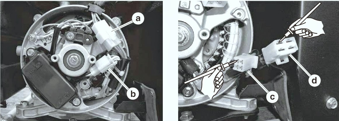
* Disconnect the generator plug (a).
The two sensing wires are the brown and blue wires that
share the same connector (b) as the wires for the DC winding; disconnect this
connector.
* Check each wire from the DC winding plug (c) with its
counterpart in the generator plug (d): blue to blue; brown to brown. In each
case there should be continuity. Also check the wires from the DC
winding plug to the generator plug, blue to brown; and brown to blue. In each
case there should be continuity.
* If the wires lack continuity in any of the tests, the
sensing wires have failed; replace the stator.
* If the wires have continuity in all cases, continue.
Check each wire from the DC winding plug to ground. (Measure
between the winding and either the outer metal case of the generator or the
ground stud on the frame.)
> If either wire has resistance to ground, it has failed.
> If both wires show no resistance to ground, they are OK.
There are two sensing wires feeding the Automatic Voltage
Regulator (AVR), one attached to each of the main windings. If the sensing
wires are shorted or broken, the AVR will not perform correctly. To check the
continuity of the sensing wires, carry out the following procedures:
Stop the engine.
* Remove the two screws which secure the end cover to the
generator and remove the end cover.
* Disconnect the yellow-, red-, black-, and green-marked wires
from the generator terminal strip (h).
The first sensing wire, represented by the brown wire on the
electrical schematic, is internal to the stator. The AVR connects to this wire
at the connection point at the upper portion of the stator. Access the wire by
disconnecting the plug (a).
To check the first sensing wire, check for continuity
between the connection point (b) where the brown wire from the AVR plug
connects and main winding 2 at the terminal strip (c) where the red-marked wire
usually connects. There should be continuity.

* If the first sensing wire does not have continuity, replace
the stator.
* If the first sensing wire has continuity, continue.
Check the first sensing wire for a short to ground. (Measure
resistance between the wire and the ground stud of the stator.)
* If the first sensing wire has resistance to ground, replace
the stator.
* If the first sensing wire has no resistance to ground,
continue.
The second sensing wire is really a circuit. It is
represented by the blue wire and then the brown wire on the electrical
schematic. This sensing circuit runs back through the Voltage Selector Switch
(VSS) where the wiring splits, with one wire running to main winding 1, another
to main winding 2. The circuit is accessed by disconnecting the plug (d) from
the connection point at the lower end of the stator. To check the circuit,
first check the main-winding-2 side. To do so, place the VSS in the 120V
position. With one lead of your multimeter, probe the blue wire (e) of the
plug. With the other lead, probe the generator terminal strip (f) where the
red-marked wire is usually connected. There should be continuity.

* Next, check the main-winding-1 side. To do so, place the VSS
in the 120V/240V position. With one lead of your multimeter, probe the blue
wire (e) of the plug. With the other lead, probe the generator terminal strip
(g) where the black-marked wire is usually connected. There should be
continuity.
* If the second sensing wire (circuit) does not have
continuity, check the wiring through the various connectors and the VSS.
* Repair or replace components as needed.
If the second sensing wire (circuit) has continuity,
continue.
* Check the blue wire for shorts to ground. (Measure
resistance between the wire and the ground stud of the stator.)
If the second sensing wire (circuit) has resistance to
ground, check the wiring through the various connectors and the VSS.
* Repair or replace components as needed.
*If the second sensing wire (circuit) has no resistance to
ground, the second sensing wire (circuit) is OK.
Confirming a Malfunctioning AVR
By removing the two sensing wires of the regulator and
measuring the output voltage of the generator, you can determine if the
generator windings and the AVR are functioning correctly. When the sensing
wires are removed from the circuit, the generator should produce high voltage
(greater than 150V, usually around 180V). If this high voltage is still
produced with the AVR’s sensing wires connected, the AVR is malfunctioning. To
check the AVR, carry out the following procedures:
* Stop the engine.
* Place the auto idle switch in the OFF position.
* Remove the two screws which secure the end cover to the
generator and * remove the end cover.
* Disconnect plugs (a and e).
* Create two short jumper wires (b and c) each with one male
spade and one female spade. Connect the jumpers between the yellow wires of the
plug (e) and where the yellow wires connect to the stator.
NOTE: Be sure to connect the jumper wires correctly.
Damage to the generator may occur if the wires are incorrectly connected.
* Start the engine and check the voltage at the terminal strip
between the wire with the yellow marking and the wire with the red
marking.
There should be approximately
180V. Also check between the wire with the green marking and the wire with the
black marking. There should be approximately 180V.
If approximately 180V is not measured, the generator winding may be bad. See section Checking Main and Rotor Winding. If approximately 180V is measured, the
generator winding are functioning properly, but the AVR is not. Replace the
AVR.