Monday, April 29, 2013

ATLAS PATIENT MONITOR - POWER SUPPLY BOARD - FUSE LOCATION'S AND MORE [MEDICAL EQUIPMENT]


POWER SUPPLY REMOVAL
  • Slide the power supply out from the E-Pac Foam.
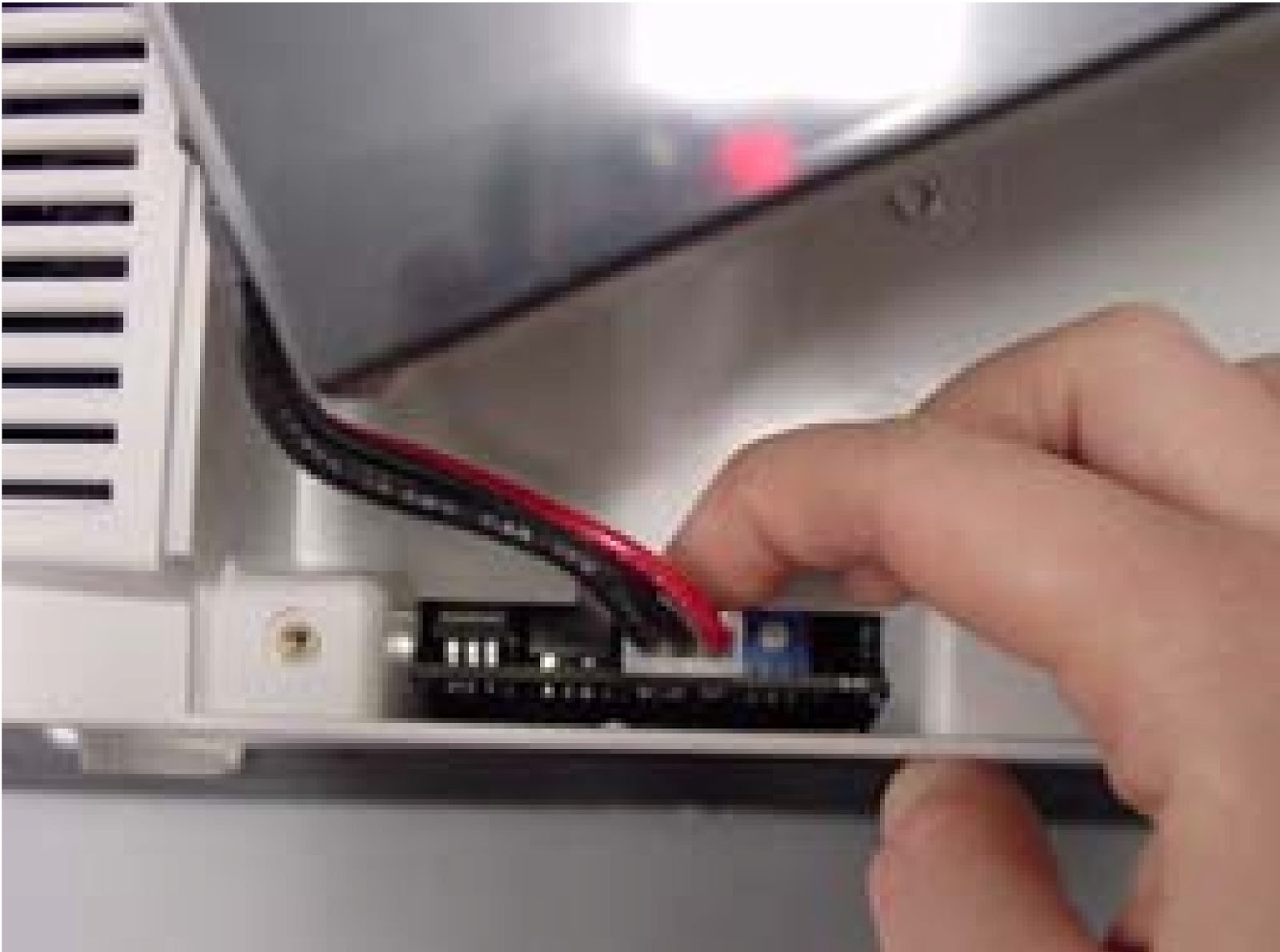
  • Power Supply Fuse Location
NOTE: Notice power supply and power supply fuse location.
  • Fan Removal
Slide fan out from E-Pac foam.
  • E-Pac Removal (Lower)
Remove lower E-Pac foam from unit.
  • Deflection PCB Removal
Carefully remove the small deflection PCB from the CRT.
  • CRT Removal
Remove the two machine screws holding CRT to the front panel.
NOTE: Notice how the ground wire is attached and is located along the side of CRT.
NOTE: The CRT and deflection PCB are factory tuned as a unit and are sold only together as a unit.
  • Display PCB Removal
Remove all 9 self-tapping screws that hold the Display PCB to the Bezel.
NOTE: Notice the correct orientation of CRT screw and washer.
  • Printer Door Button Removal
Use a small screwdriver to push the door button tab up and away from the pin that locks it onto the printer frame.
NOTE: Notice how the printer button is being removed.
  • Printer Assembly Locking Tab Release.
Pull the locking tab down and towards the front of the rear housing assembly.
  • Printer Positioning Slot Removal
Make sure printer door is open. Begin to pull the positioning slots towards the front of the rear housing and then out from the rear housing.
  • Printer Assembly Removal.
After printer positioning slots have cleared the front rear housing, pull the printer down and out of the rear housing.
  • Printer Lip Assembly.
Observe how the printer assembly fits into the lip of the rear housing.
  • Printer Cable Routing.
Observe how the printer cable lies over the printer PCB.

Sunday, April 28, 2013

ATLAS PATIENT MONITOR - DISASSEMBLE PROCEDURE & REPAIR [MEDICAL EQUIPMENT]


BATTERY REMOVAL
  • Remove the two screws holding the battery door. Remove the battery door.
  • Remove the battery connector from the main PCB. Remove battery.
Rear Housing Removal
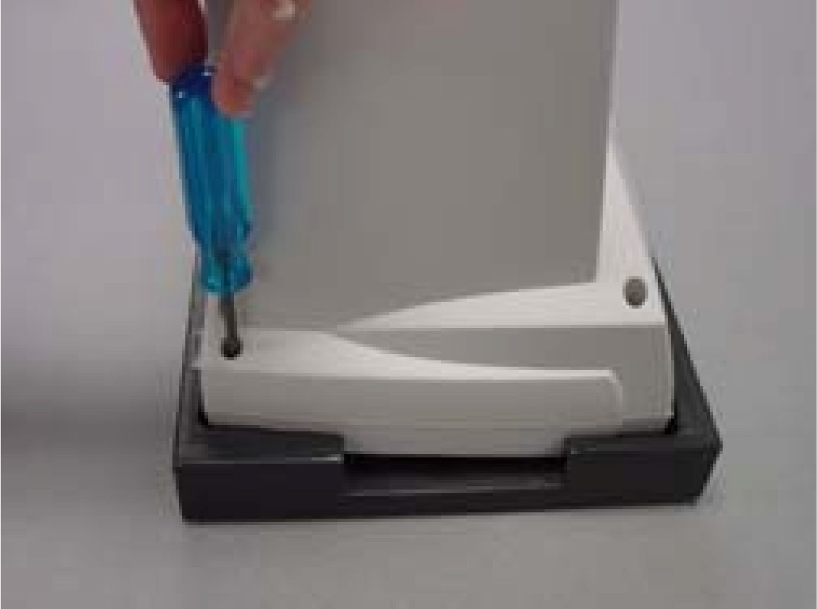
  • Remove the four Torx head machine screws. Use a #10 Torx driver.
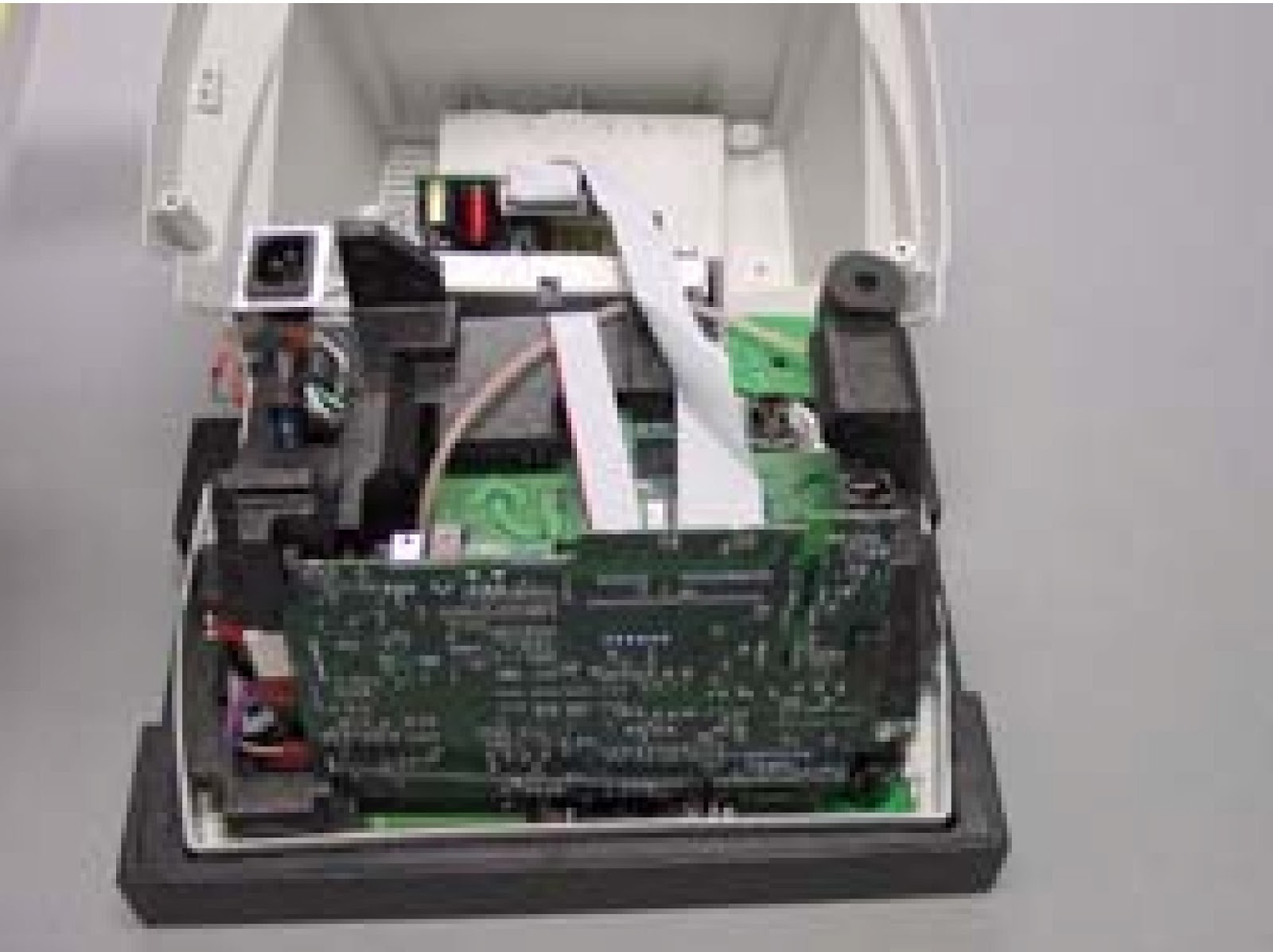
  • Pull the rear housing away from the front panel. Take special care not to damage any cables.
  • Flip the housing forward. Take special care not to damage any cables.
Observe how hose fits in E-Pac Foam. The hose fits over wiring keeping wiring secure.
Printer cable and Display Cable Removal

  • Remove both Printer and Display PCB cables from the Main PCB.
Power Supply Ground Wire Removal
  • Remove the two ground connectors from power supply chassis.
Tie Wrap Removal
  • Cut the tie wrap that secures the ground wires to the E-pac foam.
CPU Removal
  • Remove the CPU from the Main PCB.
Main PCB Removal
  • Use a tool T-16654 to pry the main Board away from the Deflection Board. Pull the E-pac tab to the right as you pry. Support the Main PCB while titling it away.
Main PCB Side Connector Removal.
  • Remove the four connectors(power supply, fan, speakers, BP pump) from the side of the main PCB.
Main PCB Hose and Wire Removal.
  • Disconnect hoses and connectors. BP hose, ecg cable, temp cable (modles 622 and 623 only, SpO2cable, CO2cable (model 623 only)and ground wire (NelcorSpO2only) from main PCB.
NOTE: Notice how hoses and connectors fit on Main PCB.
Pump Removal.
  • Remove the pump assembly from the EPac foam.
NOTE: Notice how pump fits in E-Pac Foam and how wires are routed out of pump.
CO2Exhaust Removal.
  • Remove the CO2exhaust cover and remove the CO2 connector from the E-Pac foam.
Pryon PCB Removal.

  • Remove connectors from Pryon PCB. Pull Pryon PCB from E-Pac foam.

ATLAS PATIENT MONITOR - TROUBLESHOOTING [MEDICAL EQUIPMENT]

TROUBLESHOOTING
Static Manometer Accuracy Test
Required materials.
  1. Serial interface cable
  2. PC with HyperTerminal (Windows 95 or above)
  3. 500cc vessel with inflation system.
  4. Calibrated manometer
  • Turn computer on and activate Hyper terminal. 
Hyper Terminal Settings are:
  • 9600 Baud, 8 bit word, 1 stop bit no parity, no flow control ANSI character set Start àPrograms àAccessories àCommunication àHyperTerminal
  • Turn Atlas on. 
  • Enter the following command sat the PANGEA> prompt.
PANGEA> bp safety off<ENTER>
PANGEA> bp valve close<ENTER>
Pressurize the Atlas monitor to the applied pressures in Table.
  • To compare the applied pressure to the transducer readings use the following command.
  • PANGEA> bp press<ENTER>
  • Verify that the primary transducer and secondary transducer are within the specifications listed in Table.
NOTE: The Atlas monitor will return a response to the computer screen as follows.
If you tested at the 50mmHg pressure you would receive a message similar to: px = 5279,sx = 5305 x 0.01. Where px is the primary transducer and 5279 = 52.79 mmHg and sx is the secondary transducer and 5305 = 53.05 mmHg.
BP Leak Test
NOTE: Unit must not leak more than 5 mmHg in a 15 second interval while attached to a 100cc test cavity pressurized at50 mmHg, 150 mm Hg and 250 mmHg.
  • Required Materials: 100cc test vessel (+10cc/-0cc), stopwatch, and squeeze bulb, calibrated manometer.
  • Connect Atlas to 100cc test vessel and calibrated manometer.
  • Turn Atlas on.
  • Press DATE/TIME button then press LEAD SELECT button to access the Service Mode.
  • Press SELECT button and choose Verify manometer.
  • Pressurize the Atlas with squeeze bulb to 50mmHg and allow reading to stabilize.
  • Observe pressure for 15 seconds.
  • Unit should not leak more than 5mmHg during this time.
  • Repeat this process at 150mmHg and 200mmHg.
BP Dump Verification Test
  • Connect the Atlas to a 500 cc vessel.
  • Turn Atlas on.
  • Press DATE/TIME button then press LEAD SELECT button to access the Service Mode.
  • Select Verify manometer.
  • Pressurize the Atlas to just over 260 mmHg.
  • Allow reading to stabilize for 15 seconds.
  • Ensure the reading is still over 260 mmHg.
  • Start the stop watch when you press the SELECT button. When the SELECT button is pressed the Atlas will start a pressure dump.
  • Verify that the pressure drops to below 15 mmHg within 10 seconds.
Hardware Fail Safe Tests
  • NOTE: Atlas hardware must detect over pressure on unit pneumatic system between 296.0 mmHg and 330.0 mmHg.
  • Connect the Atlas for testing.
  • Turn Atlas on.
  • Press CLOCK/DATE button then press LEAD SELECT button to access Service Mode.
  • Press SET button to highlight the Manometer.
  • Pump system up and record at what pressure the Atlas dumps.
ECG/Respiration Test
NOTE: Simulator should support ECG impedance respiration.
  • Cycle power on Atlas, connect a 5 lead ECG cable set to the simulator. Configure the simulator for NSR, 100 bpm and set the impedance respiration rate to 20.
  • Press DATE/TIME button then press TREND button to access Advanced Configuration menu.
  • Press SELECT button to highlight ECG lead set and press SET button to select 5 wire.
  • Set ECG gain to Automatic, ECG speed to 25mm/s, ECG bandwidth to Monitor, Second trace selection to ECG.
  • Press TREND button to return to idle screen.
  • Verify you see:
1. ECG cascading onto second line
2. Scale bar on top left of CRT
3. Heart rate displayed as set on simulator
4.Lead Selected = II
5. Pulse tone high pitched
  • Press LEAD Select button and step through each of the lead settings. (I,II,III,aVR,aVL,aVF,V)
  • Verify that you see a different ECG waveform for each lead selected.  Heart Rate will go to dashes and alarms on some leads.
  • Set lead selected to II.
  •  Press DATE/Time button then press Trend button to access Advanced Configuration menu.
  •  Change Second trace selection to Respiration. Press Trend button to return to idle screen.
  • Verify that you see:
1. ECG on top line
2. Scale bar on left of top line
3. Heart rate displayed as set on simulator
4. Lead Selected = II 5. Pulse tone high pitched
6. Respiration trace on second line and rate as set on simulator
7. Respiration rate displayed on CRT as set on simulator.
  • Disconnect ECG simulator.
SpO2 Test
  • Turn SpO2 alarms on.
  • Connect SpO2 cable to simulator.
  • Set simulator pulse rate to 60 beats/minute and verify that pulse rate is 60 ±3 beats/minute or3%, whichever is greater.
  • Set SpO2 between 70% and 100% and verify that SpO2 is accurate ±2 digits.

ATLAS PATIENT MONITOR - SELF TEST- FUNCTIONAL TEST - BP TEST [MEDICAL EQUIPMENTS]


SELF TEST [POWER ON]
  • Plug in Atlas into AC power with no sensors attached. Verify that the AC~ LED indictor is lit. Install paper in printer if fitted.
Turn on power and verify the following:
  • Green light in power button.
  • Loud beep when Power On button pressed.
  • Three dashes in SYSTOLIC.
  • Three dashes in DIASTOLIC.
  • Two dashes in SpO2  (takes several seconds after BP dashes come on).
  • Three dashes in PULSE (takes several seconds after BP dashes come on).
  • Single bar at the bottom of  Plethysmograph.
  • No lights in TEMP.
  • No lights in ALARMS OFF buttons.
  • X lit on AUTO.
  • CRT display may comes on slowly if cold or quickly if still warm from last use.
  • May see version string in center if comes on quickly. It isn't a problem if not seen because it comes on slowly.
On the CRT you should see:
  • Three dashes for Heart Rate
  • Heart symbol
  • Lead select symbol
  • Scale bar
  • One or two lines of dashes for wave-forms – depends upon settings.
  • Three dashes for MAP – or blank, depending upon settings.
  • Error message /(s) at bottom of screen?
On models 622 or 623, disconnect AC cable. You should see no change except the AC~ LED indicator will not be lit. If you see warnings of a low, very low or depleted battery, or if the system turns off by it’s self, plug the Atlas back into the AC outlet and let the unit charge with unit turned off. Repeat test in 2 hours.
  • Plug the monitor back into AC
MENU FUNCTIONAL TEST
  • Press DATE/TIME button to enter menu page. Press TREND button to access the Advanced Configuration menu.
  • Write down all configuration settings so that they can be reset to customer preferences later. If you have a printer press the PRINTER button to print out customer configuration settings.
  • Set language to your native tongue if necessary to allow you to write down the other settings. The top item is always the language, press either SET buttons to step through list.
  • Press TREND button to return to idle screen. Press DATE/TIME button and verify that date and time are correct. Set date and time if necessary.
NOTE:An incorrect date may indicate a battery problem. If date was incorrect, turn off unit, disconnect AC power cable, wait 5 minutes then reconnect the power cable. Turn Atlas on. Check date again. If date comes back incorrect on model 621 then replace main board. On model 622 and 623, if battery was not dead then replace main board.
  • Press DATE/TIME button to return to waveform screen if needed.
  • Press DATE/TIME button then press LEAD SELECT button to access service mode
  • Version/configuration data is in lower half of menu, write it all down.
  • Press SELECT button to highlight reset to factory defaults.
  • Press BP START/CANCEL button to reset configuration.
  • Press TREND button to return to idle screen.
  • Press DATE/TIME button then press TREND button to access the Advanced Configuration menu.
  • Set language to your native tongue if necessary
NOTE: We have just reset the monitor to factory defaults. Compare settings to factory defaults appropriate for the country in Operator manual. If the factory defaults do not match then that may indicate a memory problem. Changing only the language should not change any of the other factory default settings.
  • Press DATE/TIME button then press LEAD SELECT button to access service mode.
  • Press SELECT button to highlight CRT test pattern.
  • Press BP START/CANCEL button to show test pattern. Examine display. Press any key to end display.
  • Press Select button to highlight Printer test pattern (if fitted). Press BP START/CANCEL button to start test pattern. Printer should print a test pattern. Press any key to end  display. Examine printout.
  • Press SELECT button to highlight LED test. Press AUTO button to turn on all LEDs.  Press BP START/CANCEL button to show automatic test pattern. Watch for a while, look for glitches in pattern. Press SET button to go to manual mode and step through individual segments if needed to observe a problem.
  • Press SELECT button to highlight Button test. Press BP START/CANCEL button to start test. Press every button on system, press BP ART/CANCEL button last.
  • Verify that buttons match up with their names and that all buttons are functional.
NOTE:If name does not correspond to the button pushed then this may indicate memory corruption. You may need to replace the main board.
  • Press SELECT button to highlight Display A/D channels. Press SET button and write down all values for each of the four screens for later review. Press TREND button to return to idle screen.
BP TEST
  • Press DATE/TIME button then press TREND button to access the Advanced Configuration menu. Press SELECT button to highlight Initial pressure. Press SET button to change Initial pressure to 280 mmHg. Press SELECT button to highlight MAP. Press SET button to change MAP to Yes. Press TREND button to return to idle screen.
  • Connect the BP port to the BP simulator. Set the simulator for a normal reading (140/80, 100BPM, NSR). Press BP START/CANCEL button. Atlas should start to pump and display a manometer value in SYSTOLIC LED. This value should track and be very close to pressure displayed by manometer on BP simulator (if fitted).  Largest number shown in SYSTOLIC LED should be very close to the initial pressure setting recorded above from Advanced Configuration. System should start stepping down pressure, showing step values in SYSTOLIC LED display. It then should display the correct SYSTOLIC and DIASTOLIC values. System may show MAP value depending upon country language setting.
  • Press BP START/CANCEL button. System should start pump, display manometer value in SYSTOLIC LED. This value should track and be very close to pressure displayed by manometer in BP simulator (if fitted). Largest number shown in SYSTOLIC should be very close to the Initial pressure setting of 280 mmHg. If pressure shown exceeds 300 mmHg then re calibrate the Atlas BP.
  • System should start to step down pressure, showing step values in SYSTOLIC LED and then display correct SYSTOLIC and DIASTOLIC values. System should show MAP value. MAP value should match what simulator shows.
  • Set simulator to (120/70, 60(beats per minute)bpm, NSR).
  • Press the AUTO button. The X manual BP cycle indicator will go out and the 1 minute auto BP cycle indicator will flash for 10 seconds. 20 seconds after the 1 minute auto BP cycle indicator stops flashing, BP measurement starts.
  • Verify the BP reading. If BP measurement incorrect re-calibrate.
  • No less than 30 seconds after completing the measurement another measurement should start. While it is pumping up, press the BP START/CANCEL button.
  • Measurement should stop immediately and pressure should be dumped (as seen on the simulator manometer).
  • Press AUTO button and X manual BP cycle indicator should light (not flashing).
  • Disconnect the tubing from the BP port on the Atlas. Press BP START/CANCEL button and note the time (to the second) when the Atlas aborts the BP cycle and gives you an alarm. It should take no longer than 1 minute. Turn Atlas off.

PHILIPS - A8.0E - CHASSIS CTV - SCHEMATIC [CIRCUIT] DIAGRAMS


POWER [SMPS]
{Clcik on images to Enlarge}
HORIZONTAL DEFLECTION & LINE OUTPUT
VERTICAL DEFLECTION
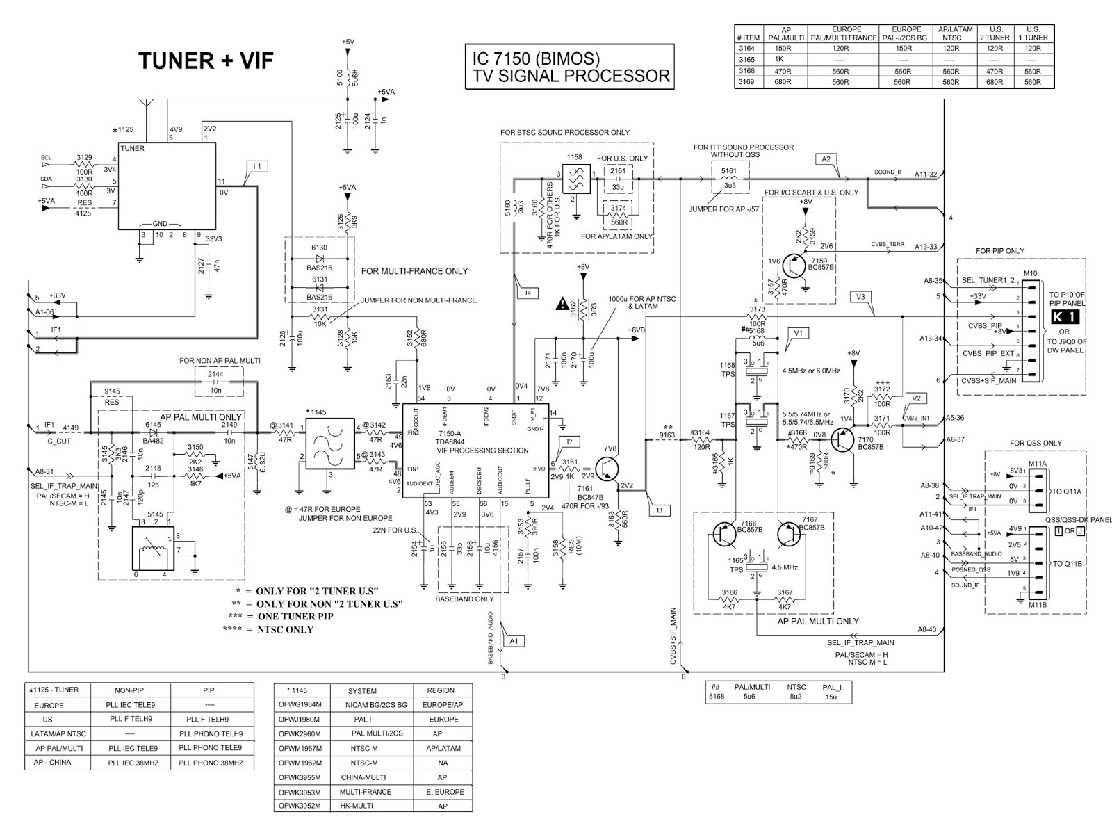
TUNER & VIDEO IF
VIDEO PROCESSING
SYNCHRONIZATION
RGB PROCESSING
CONTROLS
AUDIO PROCESSING
AUDIO OUTPUT
CRT PANEL

PHILIPS - A8.0E - CHASSIS CTV - ADJUSTMENTS _SAM_SDM


SAM [SERVICE DEFAULT MODE]
  • By transmitting the "DEFAULT" command with the RC7150 Dealer Service Tool (this works both while the set is in normal operation mode or in the SAM)
  • By shorting jumpers 9040 and 9041 on the monocarrier with a screwdriver while switching on the set.
  • By temporarily shorting jumper 9040 and 9041 when switching the set on, the 5V protection is disabled.
CAUTION:  Overriding the 5V protection should only be used for a short period of time.
Blinking LED procedure
  • When an error code is present in the error buffer, the LED will blink the number of times, equal to the value of the most current error code.
  • For recognition of the SDM, "SDM" is displayed at the upper right side of the screen.
SAM [SERVICE ALIGNMENT MODE]
  • By pressing the "VOLUME +" and "VOLUME -" buttons on the local keyboard simultaneously the set switches from SDM to SAM.
  • The purpose of the SAM is to do alignments, option settings, display/clear the error code buffer and reload default values.
Entering SAM:
  • By transmitting the "ALIGN" command with the RC7150 Dealer Service Tool (this works both while the set is in normal operation mode or in the SDM)
  • By pressing the "VOLUME +" and "VOLUME -" key on the local keyboard simultaneously when the set is in SDM.
TO EXIT SAM:
  • Switch the set to Standby (the error buffer will be erased)
  • Note: When the mains power is switched off while the set is in SAM, the set will enter to SDM immediately when the mains is switched on again.
  • In the SAM the following information is displayed on the screen:
SAM MENU
EXPLANATIONS
  1. Operation hours timer (hexadecimal)
  2. Software identification of the main micro controller (A80BBC-X.Y)

  • A80 is the chassis name for A8.0E
  • BBC is 2 letter and 1 digit combination to indicate the software type and the supported languages:
  •  X = (main version number)
  •  Y = (subversion number.
3.  Software identification of a separate Teletext or EPG micro controller (DDDD E FF)
4.  Error buffer (6 errors possible)
5.  Option bytes (7 codes possible), summary of options are explained below
6.  Sub menus are listed in a scroll-menu.
With the cursor LEFT/RIGHT keys, it is possible to:
  • (de)activated the selected menu item (e.g. LOAD DEFAULT)
  • change the value of the selected menu item
  • activate the selected submenu (e.g GEOMETRY)
Access to normal user menu
Pressing the "MENU" button on the remote control switches between the SDM and the normal user menus (with the SAM mode still active in the background). Pressing the MENU key in a sub-menu will go to the previous menu.
ERASE BUFFER
Erasing the contents of the error buffer. Select the ERASE BUFFER menu item and press the MENU RIGHT key. The contents of the error buffer is cleared.
RELOAD DEFAULT
Reloading memory default values. All default settings can be reloaded into the memory (EEPROM). Select the RELOAD DEAULT menu item and press the MENU RIGHT key. Select LOAD NOW and press MENU RIGHT to reload all settings, then switch the set to STANDBY. The default settings are activated when the set is switched on. CAUTION! Use this menu with extreme care. Otherwise customer settings will be lost.

By transmitting the "DEFAULT" command with the RC7150 Dealer Service Tool (this works both while the set is in normal operation mode or in the SAM)
By shorting jumpers 9040 and 9041 on the monocarrier with a screwdriver while switching on the set.
By temporarily shorting jumper 9040 and 9041 when switching the set on, the 5V protection is disabled.
CAUTION ! Overriding the 5V protection should only be used for a short period of time.

Blinking LED procedure
When an error code is present in the error buffer, the LED will blink the number of times, equal to the value of the most current error code.
For recognition of the SDM, "SDM" is displayed at the upper right side of the screen.