JVC LT-42DP8BG-P JVC LT-42DP8BJ-P JVCLT-42P80BU-P -
SERVICE MODE – ADJUSTMENTS - Default Data Values & ERROR
CODES
ADJUSTMENT PREPARATION
There are 2 ways of adjusting this TV :
There are 2 ways of adjusting this TV :
> One is with the REMOTE CONTROL UNIT and
the other is the conventional method using adjustment parts and components.
> The adjustment using the REMOTE CONTROL UNIT is made on the basis of the initial setting values. The setting values which adjust the screen to the optimum condition can be different from the initial setting values.
> The adjustment using the REMOTE CONTROL UNIT is made on the basis of the initial setting values. The setting values which adjust the screen to the optimum condition can be different from the initial setting values.
> Make sure that connection is correctly
made AC to AC power source.
> Turn on the power of the TV and measuring instruments for warming up for at least 30 minutes before starting adjustments.
> If the receive or input signal is not specified, use the most appropriate signal for adjustment.
> Never touch the parts (such as variable resistors, transformers and condensers) not shown in the adjustment items of this service adjustment.
PRESET SETTING BEFORE ADJUSTMENTS
Picture Mode > Standard
Picture Adjustments > Centre
Colour Temp. > Normal
Super Digipure > Auto
Movie Theatre > Auto
Colour Management > On
Picture Management > On
Zoom > Full
MEASURING INSTRUMENT AND FIXTURES
Signal generator (Pattern generator) [PAL]
Remote control unit
Signal generator (Pattern generator) [PAL]
Remote control unit
ADJUSTMENT ITEMS
VIDEO CIRCUIT
WHITE BALANCE (HIGH LIGHT) adjustment.
VIDEO CIRCUIT
WHITE BALANCE (HIGH LIGHT) adjustment.
BASIC OPERATION OF SERVICE MODE
HOW TO ENTER THE SERVICE MODE
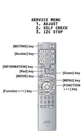
Press [INFORMATION] key and [MUTING] key on the remote control unit simultaneously to enter the SERVICE MODE SCREEN.
In the SERVICE MENU, press the [1] key to display ADJUSTMENT MODE SCREEN
HOW TO ENTER THE SERVICE MODE
Press [INFORMATION] key and [MUTING] key on the remote control unit simultaneously to enter the SERVICE MODE SCREEN.
In the SERVICE MENU, press the [1] key to display ADJUSTMENT MODE SCREEN
[Before enter the SERVICE MODE, press
the [MODE] key to confirm that "TV" position is indicated. If it is
in a wrong position, the SERVICE MODE operation cannot be performed.
When a number key other than the [1] key is pressed in the SERVICE MODE SCREEN, the other relevant screen may be displayed. This is not used in the adjustment procedure. Press the [MENU] key to return to the SERVICE MODE SCREEN.]
When a number key other than the [1] key is pressed in the SERVICE MODE SCREEN, the other relevant screen may be displayed. This is not used in the adjustment procedure. Press the [MENU] key to return to the SERVICE MODE SCREEN.]
HOW TO EXIT THE SERVICE MODE
Press the [MENU] key to exit the Service mode.
Press the [MENU] key to exit the Service mode.
SERVICE MENU SCREEN and SERVICE
MODE SELECT KEY LOCATION
Adjustment mode
This mode is used to adjust the VIDEO
CIRCUIT and the MTS CIRCUIT.
HOW TO ENTER THE ADJUSTMENT MODE
When the SERVICE MENU SCREEN of SERVICE MODE is displayed, press [1] key to enter the ADJUSTMENT MODE.
When the SERVICE MENU SCREEN of SERVICE MODE is displayed, press [1] key to enter the ADJUSTMENT MODE.
DESCRIPTION OF STATUS DISPLAY

SIGNAL SYSTEM
The signal PAL50 : PAL50Hz (Composite /
S-video)
PAL60 : PAL60Hz (Composite / S-video)
SECAM : SECAM
NTSC3 : NTSC3.58
NTSC4 : NTSC4.43
525I : 525i (Component)
525P : 525p
625I : 625i (Component)
625P : 625p
1125I5 : 1125i 50Hz
1125I6 : 1125i 60Hz
RGB5 : RGB 525i
RGB6 : RGB 625i
PCVGA : PC (VGA)
PCXGA : PC (XGA)
D625I : DVB-T 625i
H525I : HDMI 525i
H525P : HDMI 525p
H625I : HDMI 625i
H625P : HDMI 625p
H750P : HDMI 750p
H125I5 : HDMI 1125i 50Hz
H125I6 : HDMI 1125i 60Hz
--- : OTHER
ZOOM MODE
State of the SCREEN SIZE or MULTI PICTURE is displayed.
SINGLE SCREEN
State of the SCREEN SIZE or MULTI PICTURE is displayed.
SINGLE SCREEN
FULL : FULL
PANO : PANORAMIC
1609 : 16:9 ZOOM
1609S : 16:9 ZOOM SUBTITLE
1409 : 14:9 ZOOM
REGU : REGULAR
PANO : PANORAMIC
1609 : 16:9 ZOOM
1609S : 16:9 ZOOM SUBTITLE
1409 : 14:9 ZOOM
REGU : REGULAR
MULTI SCREEN
M2 : 2-pictures multi
M12 : 12-pictures multi
M12 : 12-pictures multi
PICTURE MODE
SOFT : SOFT
STD : STANDARD
BRI : BRIGHT
STD : STANDARD
BRI : BRIGHT
COLOUR TEMP.
H : COOL
M : NORMAL
L : WARM
M : NORMAL
L : WARM
SETTING ITEM NAME
Setting item name are displayed. For the setting item names to be displayed, refer to "INITIAL SETTING VALUES IN THE SERVICE MODE"
Setting item name are displayed. For the setting item names to be displayed, refer to "INITIAL SETTING VALUES IN THE SERVICE MODE"
SETTING ITEM NO
Setting item numbers are displayed. The setting item numbers to be displayed are listed below.
Setting item numbers are displayed. The setting item numbers to be displayed are listed below.
S001 - S009 Video system setting
T001 - T003 (NOT USED)
M001 - M224 (NOT USED)
F001 - F002 (NOT USED)
D001 (NOT USED)
Z001 (NOT USED)
F001 - F002 (NOT USED)
D001 (NOT USED)
Z001 (NOT USED)
SETTING VALUE (DATA)
The SETTING VALUE is displayed.
The SETTING VALUE is displayed.
CHANGE AND MEMORY OF SETTING VALUE
SELECTION OF SETTING ITEM
[FUNCTION Up / Dn key]
For scrolling up / down the setting items
SELECTION OF SETTING ITEM
[FUNCTION Up / Dn key]
For scrolling up / down the setting items
S001...S009 ↔ T001...T003 ↔ M001...M224
↔ F001...F002 ↔ D001 ↔ Z001↔return to S001
CHANGE OF SETTING VALUE (DATA)
[FUNCTION Right / Left key.
For scrolling up / down the setting values
[FUNCTION Right / Left key.
For scrolling up / down the setting values
MEMORY OF SETTING VALUE (DATA)
Changed setting value is memorized by pressing [MUTING] key.
Changed setting value is memorized by pressing [MUTING] key.
INITIAL SETTING VALUES IN THE SERVICE
MODE
Perform fine-tuning based on the "initial values" using the remote control when in the Service mode.
The "initial values" serve only as an indication rough standard and therefore the values with which optimal display can be achieved may be different from the default values. But, don't change the values that are not written in "ADJUSTMENT PROCEDURE". They are fixed values.


SELF CHECK FEATURE
This unit comes with the "Self check" feature, which checks the operational state of the circuit and displays/saves it during failure. Diagnosis is performed when power is turned on, and information input to the main microcomputer is monitored at all time. Diagnosis is displayed in 2 ways via screen display and LED flashes. Failure detection is based on input state of I2C bus and the various control lines connected to the main microcomputer.
This unit comes with the "Self check" feature, which checks the operational state of the circuit and displays/saves it during failure. Diagnosis is performed when power is turned on, and information input to the main microcomputer is monitored at all time. Diagnosis is displayed in 2 ways via screen display and LED flashes. Failure detection is based on input state of I2C bus and the various control lines connected to the main microcomputer.
HOW TO ENTER THE SELF CHECK MODE
Before enters the SELF CHECK MODE, press the [MODE] key to confirm that "TV" position is indicated. If it is in a wrong position, the SELF CHECK MODE operation cannot be performed.
> Press the [INFORMATION] key and [MUTING] key simultaneously, then enter the SERVICE MODE.
> Press the [2] key SELF CHECK MODE.
> Press the [RED] key to enter Page 2 of the SELF CHECK MODE.
[Use the [GREEN] key to toggle between Page 1 and Page 2]
[When a number key other than the [2]
key is pressed in the SERVICE MODE screen, the other relevant screen may be
displayed.
This is not used in the SELF CHECK MODE. Press the [MENU] key to return to the MAIN MENU SCREEN.]
This is not used in the SELF CHECK MODE. Press the [MENU] key to return to the MAIN MENU SCREEN.]
HOW TO EXIT THE SELF CHECK MODE
To Save Failure History
Turn off the power by unplugging the AC power cord plug when in the Self check display mode.
To Clear (Reset) Failure History
Turn off the power by pressing the [POWER] key on the remote control unit when in the Self check display mode.
To Save Failure History
Turn off the power by unplugging the AC power cord plug when in the Self check display mode.
To Clear (Reset) Failure History
Turn off the power by pressing the [POWER] key on the remote control unit when in the Self check display mode.
FAILURE HISTORY
Failure history can be counted up to 9 times for each item. When the number exceeds 9, display will remain as 9. Failure history will be stored in the memory unless it has been deleted.
Failure history can be counted up to 9 times for each item. When the number exceeds 9, display will remain as 9. Failure history will be stored in the memory unless it has been deleted.
POINTS TO NOTE WHEN USING THE SELF
CHECK FEATURE
In addition to circuit failures (abnormal operation), the following cases may also be diagnosed as "Abnormal" and counted.
Temporary defective transmissions across circuits due to pulse interruptions.
Misalignment in the on/off timing of power for I2C bus (Vcc) when turning on/off the main power. Therefore, turn on the main power, and then wait for about 3 seconds before starting Self check. If recurrences are expected, ensure to clear (reset) the failure history and record the new diagnosis results.

DETAILS


CLICK ON THE PICTURES TO MAGNIFY