Angle of View (TN Type)
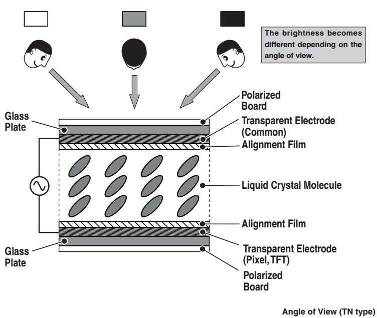
The principle of optical penetration and the interception of the LCD shutter by the arranged direction of cylindrical liquid crystal molecules controls the direction of light. Therefore, brightness, hue, and contrast depend on the direction of view of the LCD display. The range (angle) where these look normal is called the “angle of view.” The fault of the TN LCD display is that this angle of view is narrow. Fig shows that brightness changes depending on the angle the screen with a gray picture is viewed. In this figure, the liquid crystal molecule leans diagonally. Therefore, the amount of optical penetration will change depending on the angle when watching the screen from the front or the side.


The principle of optical penetration and the interception of the LCD shutter by the arranged direction of cylindrical liquid crystal molecules controls the direction of light. Therefore, brightness, hue, and contrast depend on the direction of view of the LCD display. The range (angle) where these look normal is called the “angle of view.” The fault of the TN LCD display is that this angle of view is narrow. Fig shows that brightness changes depending on the angle the screen with a gray picture is viewed. In this figure, the liquid crystal molecule leans diagonally. Therefore, the amount of optical penetration will change depending on the angle when watching the screen from the front or the side.
Multi-Domain
System
The arrangement of the TN LCD display is one directional. In this Multi-Domain System, one pixel is divided into two or more different arranged domains. Fig. 23 shows the example of Multi-Domain System with two domains. The quantity of the light per pixel from various angles is equalized by this system. Moreover, the angle of view becomes even wider by increasing the number of divisions. However, manufacturing is difficult in the rubbing process*. [The brightness of a screen is equalized as macro view]
The arrangement of the TN LCD display is one directional. In this Multi-Domain System, one pixel is divided into two or more different arranged domains. Fig. 23 shows the example of Multi-Domain System with two domains. The quantity of the light per pixel from various angles is equalized by this system. Moreover, the angle of view becomes even wider by increasing the number of divisions. However, manufacturing is difficult in the rubbing process*. [The brightness of a screen is equalized as macro view]

MVA
(Multi-domain Vertical Alignment) System
In the MVA system, the (alignment) film is arranged so that the liquid crystal molecules are stood vertically. The MVA system combines vertical alignment with the Multi-domain system. By vertically aligning the liquid crystal molecules, the influence of optical interception is lost, and the angle of view and contrast are improved.
A type of material is used that causes the liquid crystal molecules to become vertical to the glass plate without supplying voltage. (Nega-Nematic liquid crystal*)
In the MVA system, attaching the boss by resin and making the liquid crystal molecules stand diagonally on the transparent electrode make multiple alignment domains. Therefore, since the rubbing process can be skipped at the alignment film production, manufacturing becomes easier compared with the multidomain system. Generally, a Posi-Nematic system is used that aligns the liquid crystal molecules by supplying voltage.

IPS (In-Plain Switching) System
The structure of an IPS system is shown in Fig. 25. The pixel and common electrodes are mounted to the transparent film (drive transistor) side and the electric field is generated horizontally to the glass plate. With this electric field, the alignment direction of liquid crystal molecules is rotated 90º in parallel to the glass plate.
In the IPS system, liquid crystal molecules rotate all at once in the horizontal direction. Since these liquid crystal molecules do not lean like the TN type, there is little change in the picture characteristics (contrast, brightness, hue, etc.) and the angle of view becomes wider. However, there are a few problems. The quantity of transparent light is reduced, slower response speed, and a white picture becomes a little bluish or yellowish depending on the viewing direction. The S-IPS (Super-IPS) type was developed to improve upon these problems. In the S-IPS type, the structure of the electrode for driving the liquid crystal molecules becomes a zigzag form, which reduces the change of color, increases the viewing angle to about 160º and has high definition equivalent to a CRT.

Optically Compensated Film
By using the optically compensated film, the phase shift of the STN type of LCD display is corrected, and the angle of view and contrast are improved. Three methods for attaching the optically compensated film are shown in Fig.

OCB (Optically Compensated Birefringence) System
The OCB system combines the bend-alignment system where the liquid crystal molecules are bent and aligned between the upper and lower boards and optically compensation film. This system has the features of increased angle of view and quicker response speeds. However, bend-alignment is difficult to make uniform and stable.

Improvement
of Response Speed. Inpulse System
In order to reduce afterimage and dim outline, there is the system that has the backlight blinked for every writing of one picture or an all black picture in inserted in the fixed cycle. It is called the “Inpulse System.”
For example, with the system called “Super Inpulse System,” the black data is written in every 1/60 second, and the afterimage and the ghosts are reduced.
With
the usual LCD panel, since the picture is displayed continuously, the front
picture becomes dim as the afterimage. In
the impulse system, by inserting black data between the picture data, the
afterimage is reduced and the high-speed response is improved.

FFD
(Feed Forward Driving) System
The response speed of LCD brightness can be improved by adding over-shoot characteristic to the data line voltage.
The response speed of LCD brightness can be improved by adding over-shoot characteristic to the data line voltage.