Sony KDL-32EX301 KDL-32EX500 KDL-46EX400 KDL-32EX400 KDL-40EX500 KDL-46EX500 KDL-40EX400 KDL-40EX501 KDL-46EX501 KDL-40EX401
Protection
Mode Symptom Troubleshooting
The
KDL-32S5100 and KDL-32XBR9 include the following protection mode blink patterns
(or self-diagnostics).
[All
red protection mode LED blink patterns occur using the Standby-LED at the lower
left front of the TV.]
Failure
Symptoms: 2X
Blink - Main Power Error
A 2X protection mode blink pattern can be activated due one of the following
defects on the G2LE-Board, G2HE, GD2-Board..
Loss of AU12V (LVP)#
Excessive AU12V Level (OVP)#
Loss of AU12V (LVP)#
Excessive AU12V Level (OVP)#
Excessive
24V Level (OVP) (32” & 40” models)
Excessive PFC Voltage (OVP)
Excessive PFC Temperature (OTP)
# Low Voltage Protection (LVP)
# Over Voltage Protection (OVP)
Excessive PFC Voltage (OVP)
Excessive PFC Temperature (OTP)
# Low Voltage Protection (LVP)
# Over Voltage Protection (OVP)
A
loss or excessive condition of the AU12Vdc secondary voltage from the main
power supply IC6501 will cause a 2X blink pattern on the StandbyLED. The 12Vdc
can be checked at CN6401/pin 4. The If the measurement is 0V or rises above
12Vdc (approaches 15V) before the TV shutdown the G2LE-Board, G2LE, GD2-Board
is defective. If approximately 12Vdc is
present and remains below 12Vdc before shutoff then the A-Board is defective. An excessive 24Vdc (32” & 40” models)
secondary voltage from the main power supply IC6501 will also cause a 2X blink
pattern on the StandbyLED. The 24Vdc can be measured at CN6402/pin 3 before TV
shutdown. If the voltage rises above the
24V level (approaches 27) before TV shutdown then the power supply is
defective, replace the G2LE, G2HE , GD2-Board to fix the problem.

Finally, there are PFC protection circuits on the power supply board that when activated will cause a 2X blink protection mode. The PFC circuit is monitor for both over-voltage and over-temperature. Therefore, if the AU12V and 24V circuits checkout okay, there could still be a problem on the power supply board in the PFC circuit causing the 2X blink. Replace the G2LE, G2HE, GD2-Board to fix this condition.
3X Blink- Audio Error
The Audio error can occur due one of the following error conditions.
Shorted or Damaged Speaker Connections
Defective Audio Amplifier (A-Board)
Loss of AU12V (Open F1 on A-Board)
The first thing to check when a 3X blink protection mode occurs is the physical condition of the speakers and speaker connections. The speakers should measure 8 ohms. Shorted speakers or connections can cause a 3X blink protection mode. If the speakers and connections check okay, then the defective component is on the A-Board. Either a open F1 or defective audio amplifier will cause a 3X blink protection mode. In either case, replace the A-Board to fix this condition.
LED Blinking Codes

4X
Blink - Balancer Failure (46” Models ONLY)
In most cases, a 4X protection mode indicates a defective lamp or lamps. Therefore, replace the LCD panel to fix this condition. If the 4X protection is still present after replacing the LCD panel, there could be a problem on the A-Board or GD2-Board. First replace the A-Board then the GD2- Board.
In most cases, a 4X protection mode indicates a defective lamp or lamps. Therefore, replace the LCD panel to fix this condition. If the 4X protection is still present after replacing the LCD panel, there could be a problem on the A-Board or GD2-Board. First replace the A-Board then the GD2- Board.
5X
Blink - TCON & HFR Failure
The 5X blink protection mode indicates a communications error between the TCON/HFR board and the MT5388 microprocessor on the A-Board. First replace the TCON/HFR Board if the 5X protection mode blink pattern occurs. If the TCON/HFR Board does not repair the problem then replace the A-Board.
The 5X blink protection mode indicates a communications error between the TCON/HFR board and the MT5388 microprocessor on the A-Board. First replace the TCON/HFR Board if the 5X protection mode blink pattern occurs. If the TCON/HFR Board does not repair the problem then replace the A-Board.
6X
Blink - Backlight System Failure (32” & 40” Models)
NOTE: All models will make three attempts to power up before a 6X error is activated. The SONY logo (Backlight) will display on the screen and the tones (with Volume up) will be heard three times. After the third attempt the TV will turn off and the Standby LED will blink a 3X protection mode. In most cases, if the backlight momentarily illuminates and the TV shuts off and a 6X is activated than one or more of the backlight lamps are defective. The LCD Panel assembly panel must be replaced for a defective lamp. If a 6X blink pattern is activated than a defect has occurred in one of the following areas.
NOTE: All models will make three attempts to power up before a 6X error is activated. The SONY logo (Backlight) will display on the screen and the tones (with Volume up) will be heard three times. After the third attempt the TV will turn off and the Standby LED will blink a 3X protection mode. In most cases, if the backlight momentarily illuminates and the TV shuts off and a 6X is activated than one or more of the backlight lamps are defective. The LCD Panel assembly panel must be replaced for a defective lamp. If a 6X blink pattern is activated than a defect has occurred in one of the following areas.
Defective Panel Lamp(s)
Defective Backlight Inverter Board
Defective TV Microprocessor
Defective 24V Power Supply
When troubleshooting a 6X backlight system failure it is key to notice if the backlights illuminate before the TV shuts off. The following list shows the possible backlight status and blink pattern and the possible failed components.
1) Momentary Backlight and 6X
a) Defective Lamp(s)
b) Defective Backlight Inverter Board
2) No Backlight and 6X
a) Defective TV Microprocessor
b) Defective 24V Power Supply
c) Defective Backlight Inverter Board.
[Before
replacing the LCD Panel assembly check the backlight Inverter Board outputs. A
failure of one of the inverter outputs will also cause this same symptom
(Momentary Backlight & 6X). If there
is no backlight before the TV shuts off and activates a 6X, than check the
“Backlight ON” signal from the TV microprocessor and the 24V power supply from
the G2LE, G2HE, GD2-Board. If the
“Backlight ON” and 24V power supply are okay than the Backlight Inverter board
has failed and must be replaced. This will be a rare occurrence but the
Inverter board can cause a “No Backlight” condition and must be considered.]
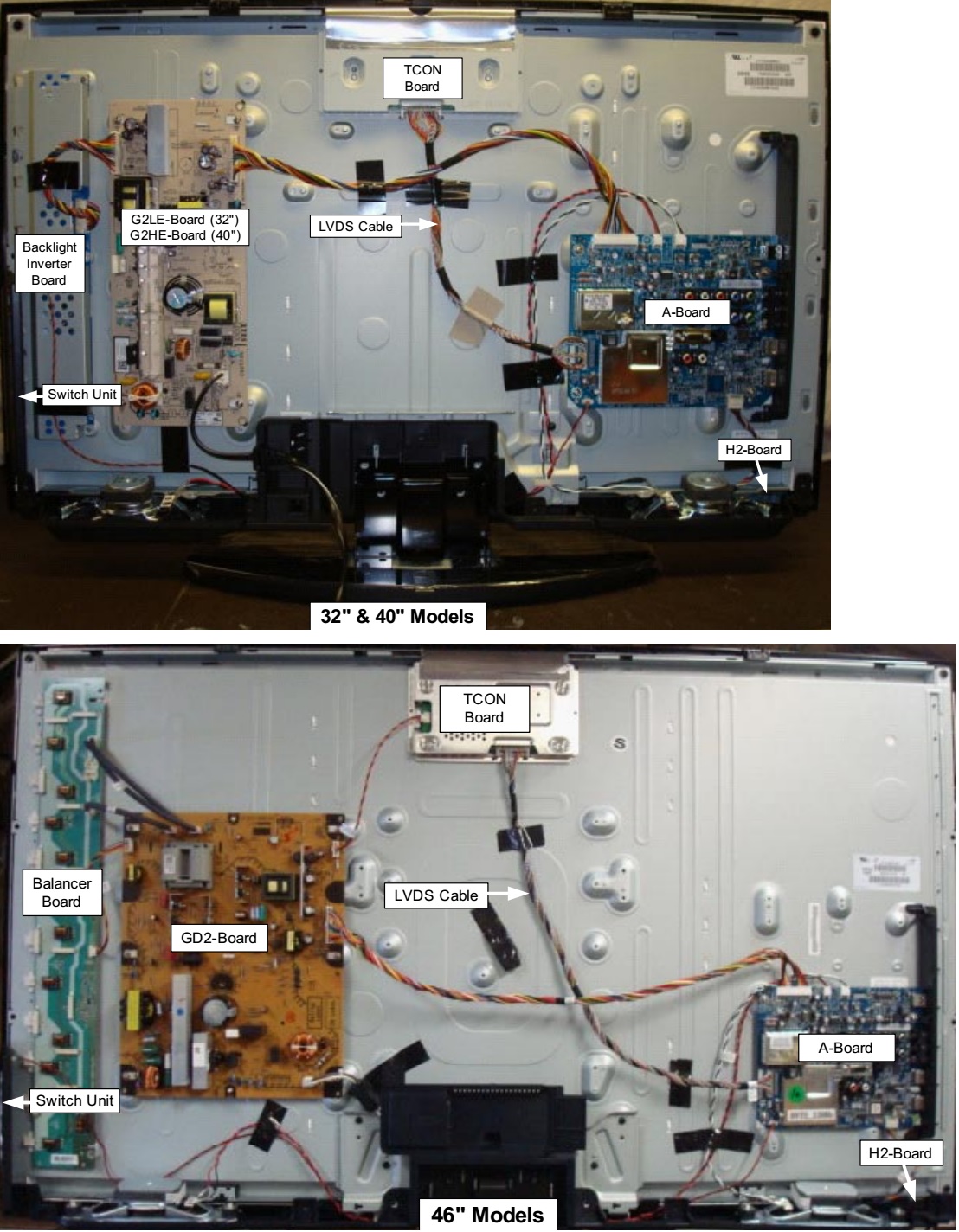
PWB Location
 6X Blink - Backlight System Failure (46” Models)
PWB Location
The 46” models have both a 4X and 6X blink protection mode. The 4X blink will, in most cases, be caused by a defective lamp. Because all the Backlight HV Inverter circuits are located on the GD2-Board, a 6X blink protection mode will be fixed, in most cases, by replacing the GD2-Board. If the GD2-Board does not repair the problem replace the A-Board. The BL-ON and Dimmer signals come from the microprocessor on the A-Board. A shorted or open BL-ON signal will cause this 3X condition. Also a shorted Dimmer will cause this 3X condition.
7X Blink - Temperature Failure
These models do not display a temperature warning OSD dialogue box before shutting-off and going into a 7X Standby-LED blink pattern. It will just shut-off and activate a 7X without any usually warning on the screen.
The main objective when a 7X blink pattern occurs is to determine which of the following possible defects is causing the excessive temperature condition.
Excessive Ambient Room Temperature
Dust or Debris Blocking the TV Ventilation Apertures
Defective Temperature Sensor IC4305 or MT5388 microprocessor (A-Board)
The first step is to notice how long it takes the TV to shut-off and trigger a 7X blink protection mode.
If the TV has an actual excessive temperature condition it will take a considerable period of time to shut-off and indicate a 7X blink protection mode. This is because it will take time for the TV to heat up and for the temperature sensor to detect the excessive temperature and shut the TV off If the TV takes a considerable period of time to shut-off check the following items:
The TV should not be located too close to any heating elements.
The TV should have at least 4 inches of clearance around all sides to ensure adequate ventilation.
Check that all vented areas on the TV are clear of all Dust and Debris.
If the TV shuts-off immediately (Not an Actual Excessive Temperature Condition) after Power-ON then one of the following components has failed.
Main Microprocessor IC3002 (A-Board)
Temperature Sensor IC3502 (A-Board)
In either case the A-Board must be replaced to fix the problem.