DP132 LG DVD player - Troubleshooting
NO BOOTING WHEN YOU TURN THE UNIT ON
When you plug power cord and turn the unit on, LED light won’t turn red, the unit won’t
read disc normally.
Check every output voltage.
1) Please check if output voltage 3.3 V from main board Q4 C polarity is normal.
è If output voltage 3.3 V is not normal, please check the working status of SMPS board.
2) Please check if output voltage 5 V from main board XP9 pin11 is normal.
è If output voltage 5 V is not normal, please check the working status of SMPS board.
3) Please check if output voltage 1.2 V from main board Q5 C polarity is normal.
è If output voltage 1.2 V is not normal, please check the working status of main board Q5

When you plug power cord and turn the
unit on, LED light won’t turn red, the unit won’t
read disc normally.
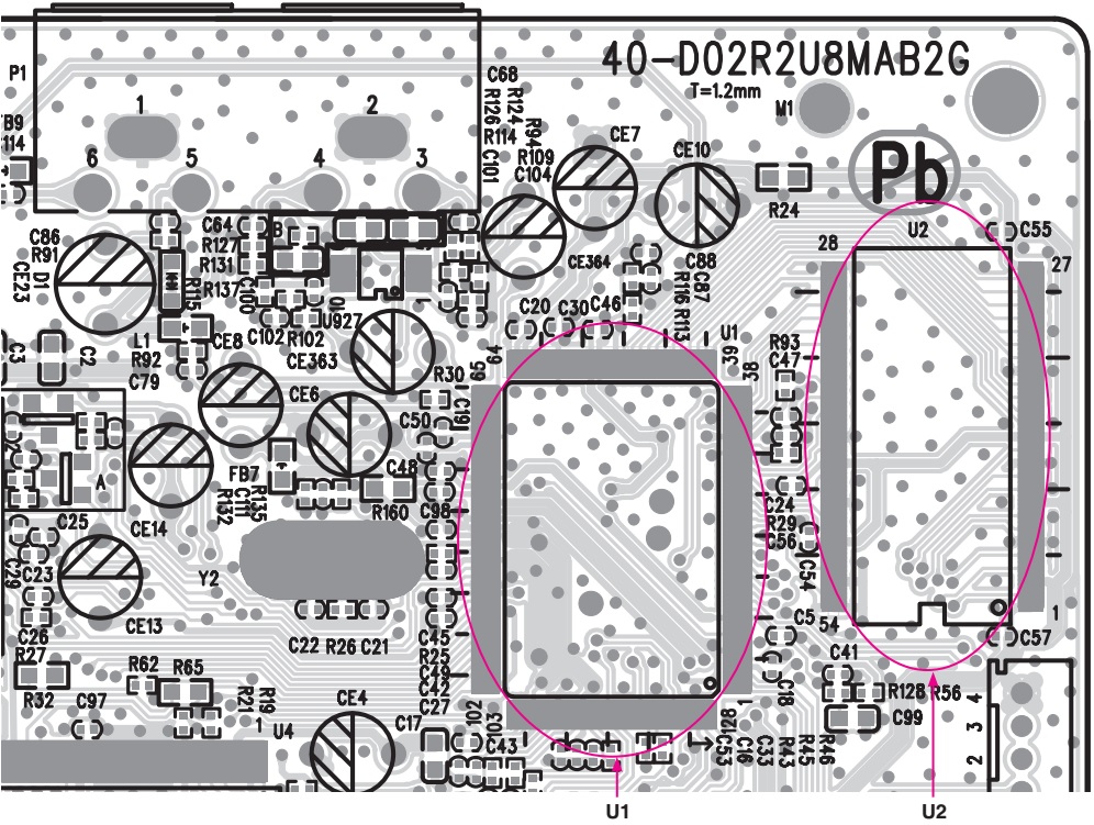
Check main board IC U1 signal and its peripheral circuit.
1) Please check if output voltage 3.3 V from U1 pin4, pin32, pin78, pin83 is normal.
è If output voltage 3.3 V is not normal, please check 3.3 V power circuit of main board.
2) Please check if output voltage 1.2 V from U1 pin10, pin77, pin86 is normal.
è If output voltage 1.2 V is not normal, please check 1.2 V power circuit of main board.
3) Please check if oscillating frequency 27 MHz of main board Y2 crystal is normal.
è If oscillating frequency 27 MHz is not normal, please check if Y2 and its peripheral circuit is in failure.
4) Please check if frequency 135 MHz of U1 pin31 RAM_CLK is normal.
è If oscillating frequency 135 MHz is not normal, please check if U1 is in failure.
read disc normally.
Check main board IC U1 signal and its peripheral circuit.
1) Please check if output voltage 3.3 V from U1 pin4, pin32, pin78, pin83 is normal.
è If output voltage 3.3 V is not normal, please check 3.3 V power circuit of main board.
2) Please check if output voltage 1.2 V from U1 pin10, pin77, pin86 is normal.
è If output voltage 1.2 V is not normal, please check 1.2 V power circuit of main board.
3) Please check if oscillating frequency 27 MHz of main board Y2 crystal is normal.
è If oscillating frequency 27 MHz is not normal, please check if Y2 and its peripheral circuit is in failure.
4) Please check if frequency 135 MHz of U1 pin31 RAM_CLK is normal.
è If oscillating frequency 135 MHz is not normal, please check if U1 is in failure.

When you plug power cord and turn the unit on, LED light won’t turn red, the unit won’t read disc normally.
Check main board IC U2 signal and its peripheral circuit.
1) Please check if output voltage 3.3 V from IC U2 pin1, 3, 9, 14, 27, 43, 49 is normal.
=>If output voltage 3.3 V is not normal, please check 3.3 V power circuit of main board.
Check every signal connected between IC U2 and IC U1, especially including DATA and ADDRESS signal.
=> If DATA and ADDRESS signal is not normally output, please check if U2 is in failure.
When you plug power cord and turn the
unit on, LED light won’t turn red, the unit won’t read disc normally.
Check main board IC U3 signal and its peripheral circuit.
1) Please check if output voltage 3.3 V from IC U3 pin8 is normal.
è If output voltage 3.3 V is not normal, please check 3.3 V power circuit of main board.
2) Please check every signal connected between IC U3 and IC U1, especially including CE,DATA and CLK signal.
è If CE, DATA and CLK signal is not normally output, please check if U3 is in failure.

When you plug power cord and turn the unit on, LED light won’t turn red, the unit won’t read disc normally.
Please check main board IC U4 singal and its peripheral circuit.
1) Please check if output voltage 5 V from U4 pin8, pin19 is normal.
=> If output voltage 5 V is not normal, please check 5 V power circuit of main board.
2) Please check every singal connected between IC U4 and IC U1, especially including F+, F-, T+, T-,SP+, SP-, SL+, SL- signal to drive MD.
=> If F+, F-, T+, T-, SP+, SP-, SL+, SL- signal is not normally output, please check if U4 is in failure.

NO VIDEO OUTPUT WHEN YOU TURN THE UNIT
ON
When you plug power cord and turn the unit on, LED light will turn red, the unit will read disc normally, but it won’t have video output.
1. Please check the solder joint status of main board connector P1.
è If P1 has cold solder joint, P2 pins should be oxidized, and please replace P1.
2. Please check CVBS signal of main board IC U1 pin69.
è If CVBS signal is not normally output, please check if U1 is in failure.


NO AUDIO OUTPUT WHEN YOU TURN THE UNIT
ON
When you plug power cord and turn the unit on, LED light will turn red, the unit will read disc normally, but it won’t have audio output.
1. Please check the solder joint status of main board connector P1.
è If P1 has cold solder joint, P1 pins should be oxidated, and please replace P1.
2. Please check the working status of main board IC U927.
è If output voltage 5 V from U927 pin7 is not normal, please check 5 V power circuit of main board.
ÖIf AL and AR signal from U927 pin1, pin2, pin9, pin10 is not normally output, please check if U927 is in failure.
3. Please check the working status of main board IC U1.
è If AL and AR signal from U1 pin65, pin66 is not normally output, please check if U1 is in failure.