Sharp AX-1100(R)M - AX-1100(SL)M - MICROWAVE
OVEN WITH STEAM AND GRILL

Sharp recommend that wherever possible fault-finding is carried
out with the supply disconnected. It may, in some cases, be necessary to
connect the supply after the outer case has been removed, in this event carry out
3D checks and then disconnect the leads to the primary of the power
transformer. Ensure that these leads remain isolated from other components and
the oven chassis. (Use insulation tape if necessary.) When the testing is
completed, carry out 3D checks and reconnect the leads to the primary of the
power transformer.
TO CHECK 3D
1) Disconnect the supply.
2) Door opened, and wedged open.
3) Discharge the high voltage capacitor.
2) Door opened, and wedged open.
3) Discharge the high voltage capacitor.
[The high-voltage capacitor remains charged about 60 seconds after
the oven has been switched off. Wait for 60 seconds and then short-circuit the
connection of the highvoltage capacitor (that is, of the connecting lead of the
high-voltage rectifier) against the chassis with the use of an insulated
screwdriver.]
TO CHECK 4R
1) Reconnect all leads removed from components during testing.
2) Replace the outer case (cabinet).
3) Reconnect the supply.
4) Run the oven. Check all functions.
2) Replace the outer case (cabinet).
3) Reconnect the supply.
4) Run the oven. Check all functions.
Microwave ovens should not be run empty. To test for the presence
of microwave energy within a cavity, place a cup of cold water on the oven
turntable, close the door and set the power level to HIGH (100%). And set the
microwave timer for two (2) minutes. When the two minutes has elapsed (timer at
zero) carefully check that the water is now hot. If the water remains cold,
carry out 3D checks and re-examine the connections to the component being tested.
Some normal boards are found in board units that have been
returned due to oven failure. So, most of board replacements may arise from
poor harness connection. Accordingly, before replacing any board that was
judged to require its replacement, use the following procedure to re-check that
the connection terminal of a connector has been properly inserted:
When the connectors have been incorrectly inserted to the control
unit.
CN-A > The oven can not be powered on. (Fan motor, oven lamp, damper motor and /or
pump motor do not operate.)
CN-B > No heating can be done. Thermistor error EE01 or EE12
appears.
RY1 > Antenna motor, high voltage transformer, oven lamp,
engine heating element, and grill heating element do not operate.
RY2 > Engine heating element does not operate.
RY3 > Grill heating element does not operate.
RY4 > Antenna motor and high voltage transformer do not
operate.
2. When latch switch adjustment is incorrect
When latch switch adjustment is incorrect, symptoms such as no heating, no heating start, no activation even with start button pressed, etc. will occur.
3. Final error code is memorized in ROM (control unit). (Refer to Error list EE code on page 10-1.)
4. When the intake damper motor is locked or wire leads to it are not connected, cooking mode is stopped minute after starting cooking.
5. minutes after stopping cooking, energy save mode will work and no segment is displayed.
How to operate the test mode


Error List
Operate test mode
(Power on and door closed) ® STOP ® STEAM HIGH ® MICRO ® Door open ® Select Test No. 2by [WEIGHT UP/ DOWN] ® START ® Select Address 04h (or 05h) ® START
EE code: EE code is memorized in the FLASH address 04h as error history. (Only antenna error code is memorized in the FLASH address 05h.)
NOTE: When an error mode occurs except for shortage of water error and the oven stopping state continues for more than 3 minutes, the oven will be powered off by Energy save mode function.

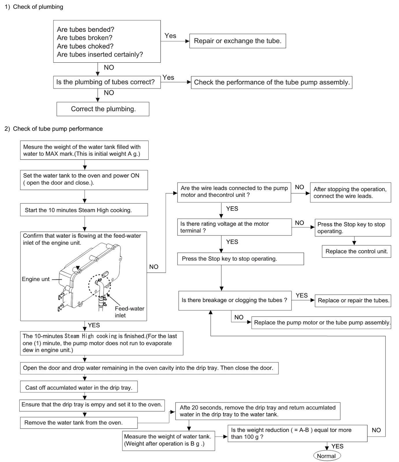
How to check in the event of an error
Check
the plumbing of the tubes.
If the plumbing is normal, check the performance of the tube pump assembly.
If the plumbing is normal, check the performance of the tube pump assembly.


CLICK ON THE TABLES TO ZOOM IN
To be continued