Wiring Diagram_Circuit
Diagram_Interlock Mechanism adjustments_Disassembly_DAEWOO
KOM-9F0CKS_KOM-9F0CTS _ Microwave Oven


DIS-ASSEMBLY AND ASSEMBLY
Unlike many other appliances, the microwave oven is
high-voltage, high-current equipment.
It is completely safety during normal operation.
However, carelessness in servicing the oven can result in an electric shock or possible danger from a short circuit.
It is completely safety during normal operation.
However, carelessness in servicing the oven can result in an electric shock or possible danger from a short circuit.
1. Always remove the power plug from the outlet before servicing.
2. Use an insulated screwdriver and wear rubber gloves when servicing the high voltage side.
3. Discharge the high voltage capacitor before touching any oven components or wiring.
2. Use an insulated screwdriver and wear rubber gloves when servicing the high voltage side.
3. Discharge the high voltage capacitor before touching any oven components or wiring.
Check the grounding.
Do not operate on a 2-wire extension cord.
The microwave oven is designed to be used with grounded.
It is imperative, therefore, to make sure it is grounded properly before beginning repair work.
Do not operate on a 2-wire extension cord.
The microwave oven is designed to be used with grounded.
It is imperative, therefore, to make sure it is grounded properly before beginning repair work.
Warning about the electric charge in the high voltage capacitor.
For about 30 seconds after the operation stopped and electric charge remains in the high voltage capacitor.
When replacing or checking parts, short between oven chassis and the negative high terminal of the high voltage capacitor, by using a properly insulated screwdriver to discharge.
For about 30 seconds after the operation stopped and electric charge remains in the high voltage capacitor.
When replacing or checking parts, short between oven chassis and the negative high terminal of the high voltage capacitor, by using a properly insulated screwdriver to discharge.
4. When the 20A fuse is blown out due to the operation of the
monitor switch; replace primary interlock switch, secondary interlock switch
and interlock monitor switch.
5. After repair or replacement of parts, make sure that the screws are properly tightened, and all electrical connections are tightened.
6. Do not operate without cabinet.
5. After repair or replacement of parts, make sure that the screws are properly tightened, and all electrical connections are tightened.
6. Do not operate without cabinet.
[When servicing the
appliance, need a care of touching or replacing high potential parts because of
electrical shock or exposing microwave. These parts are as follows - HV
Transformer, Magnetron, HV Capacitor, HV Diode.]
To remove cabinet
1) Remove twelve screws on cabinet.
2) Pull the cabinet backward.
1) Remove twelve screws on cabinet.
2) Pull the cabinet backward.
To remove control panel assembly
1) Remove three screws which secure the front plate.
2) Remove the control panel assembly from front plate of cavity.
3) Reverse the above for reassembly.
1) Remove three screws which secure the front plate.
2) Remove the control panel assembly from front plate of cavity.
3) Reverse the above for reassembly.
To remove door assembly
1) Open the door assembly and lift the door assembly.
2) Reverse the above for reassembly.
1) Open the door assembly and lift the door assembly.
2) Reverse the above for reassembly.

DOOR ASSEMBLY [To remove door parts.]
1) Remove the gasket door from the door assembly.
2) Remove nine screws from the door assembly.
3) Remove the door sub assembly from the door assembly.
4) Remove the stopper hinge *t assembly from the door painting assembly.
5) Remove the spring and the hook.
6) Remove the barrier screen *o from frame door.
7) Remove two screws from frame door.
8) Remove the handle door assembly from frame door.
9) Remove the screw from the handle door assembly.
10) Reverse the above steps for reassemble.

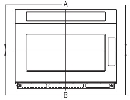
Method to reduce the gap between the
door seal and the oven front surface.
To reduce gap located on part ‘A’
• Loosen screws on top of lock and then, close the door with adjusting gap of front surface of oven.
• Tighten screw.
(2) To reduce gap located on part ‘B’
• Loosen screws on under of lock and then, close the door with adjusting gap of front surface of oven.
• Tighten screw.
• Loosen screws on top of lock and then, close the door with adjusting gap of front surface of oven.
• Tighten screw.
(2) To reduce gap located on part ‘B’
• Loosen screws on under of lock and then, close the door with adjusting gap of front surface of oven.
• Tighten screw.
[A small gap may be acceptable if the microwave leakage does not
exceed 4mW/cm2.]
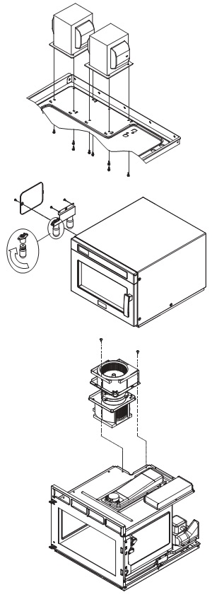
To remove high voltage capacitor.
Remove each two screws which secure fore cover exhausts.
2) Remove fourteen screws which secure rear plate assembly.
3) Remove each screw which secures two grounding ring terminal of the H.V. diode and two capacitor holder.
4) Remove two H.V. diode from the capacitor holder.
5) Reverse the above steps for reassembly.
2) Remove fourteen screws which secure rear plate assembly.
3) Remove each screw which secures two grounding ring terminal of the H.V. diode and two capacitor holder.
4) Remove two H.V. diode from the capacitor holder.
5) Reverse the above steps for reassembly.
To remove magnetron.
1) Remove each four nuts which secure the magnetrons.
2) Remove the two magnetrons.
3) Reverse the above steps for reassembly.
2) Remove the two magnetrons.
3) Reverse the above steps for reassembly.


[Never install the magnetron
without the metallic gasket plate which is packed with each magnetron to
prevent microwave leakage. Whenever repair work is carried out on magnetron,
check the microwave leakage. It shall not exceed 4mW/cm2 for a fully assembled
oven with door normally closed.]
To remove PCB main manual AS,
noise-filter.
1) Remove six screws PCB main manual AS.
2) Remove two screws noise-filter.
3) Reverse the above steps for reassembly.
1) Remove six screws PCB main manual AS.
2) Remove two screws noise-filter.
3) Reverse the above steps for reassembly.

To remove H.V.transformer.
1) Remove each four screws holding the H.V. transformer.
2) Remove the H.V.transformer.
3) Reverse the above steps for reassembly.
1) Remove each four screws holding the H.V. transformer.
2) Remove the H.V.transformer.
3) Reverse the above steps for reassembly.
To remove lamp.
1) Remove one screw holding the cover ramp.
2) Remove counterclockwise direction lamp from the bracket lamp.
3) Reverse the above steps for reassembly.
1) Remove one screw holding the cover ramp.
2) Remove counterclockwise direction lamp from the bracket lamp.
3) Reverse the above steps for reassembly.
To remove motor syncro.
1) Push left side of stopper in centre of cover stirrer and separate it from cavity.
2) Hold side stoppers of ceiling cover with both hands and pull down. Then take off the Ceiling Cover out of the oven cavity
3) Remove three fixture supporter stirrer holding the stirrer *t.
4) Remove stirrer *t from the cavity.
5) Insert a flat-head type screwdriver tray front equivalent approx.
6) Carefully lift up the floor tray by using the screwdriver until the floor shelf is lifted up over the level of oven opening front.
7) Remove tray from the cavity.
8) Remove three fixture supporter stirrer holding the stirrer *u.
9) Remove stirrer *u from the cavity.
10) Remove two screws holding the motor syncro.
11) Remove motor syncro from the cavity.
12) Reverse the above steps for reassembly.
[When replacing the moving antenna, make sure the plastic
stirrer spacers are correctly in place.]

INTERLOCK
MECHANISM AND ADJUSTMENT
The door lock mechanism is a device which has been specially
designed to completely eliminate microwave radiation when the door is opened
during operation, and thus to perfectly prevent the danger resulting from the
leakage of microwave.
Primary interlock switch and interlock
monitor switch
When the door is closed, the hook locks the oven door. If the door is not closed properly, the oven will not operate.
When the door is closed, the hook pushes the lock lever upward. The lock lever presses the button of the primary interlock switch to bring it under NO condition. The lock lever presses the button of the interlock monitor switch to bring it under NO condition.
D.O.M switch
When the door is closed, the hook pushes the lock lever upward. The lock lever presses the button of the primary interlock switch to bring it under NO condition.
When the door is closed, the hook pushes the lock lever upward. The lock lever presses the button of the primary interlock switch to bring it under NO condition.
ADJUSTMENT
Interlock monitor switch
When the door is closed, the interlock monitor switch should be changed (NO condition) before other switches are closed.
When the door is opened, the interlock monitor switch should be changed (NC condition) after other switches are opened.
Interlock monitor switch
When the door is closed, the interlock monitor switch should be changed (NO condition) before other switches are closed.
When the door is opened, the interlock monitor switch should be changed (NC condition) after other switches are opened.
Adjustment steps
a) Loosen two mounting screws.
b) Adjust interlock switch assembly position.
Actuation distance of primary and secondary interlock switch shall be adjusted almost 0mm.
c) Make sure that lock lever moves smoothly after adjustment is completed.
d) Tighten completely two mounting screws.
a) Loosen two mounting screws.
b) Adjust interlock switch assembly position.
Actuation distance of primary and secondary interlock switch shall be adjusted almost 0mm.
c) Make sure that lock lever moves smoothly after adjustment is completed.
d) Tighten completely two mounting screws.
[Microwave emission test should be performed after adjusting
interlock mechanism. If the microwave emission exceeds 4mW/cm2, readjust
interlock mechanism.]

COMPONENT TEST PROCEDURE
> High voltage is present at the high voltage terminal of the high voltage transformer during any cooking cycle.
> It is neither necessary nor advisable to attempt measurement of the high voltage.
> Before touching any oven components or wiring, always unplug the oven from its power source and discharge the capacitor.
1. High voltage transformer
(1) Remove connections from the transformer terminals and check continuity.
(2) Normal readings should be as follows :
Secondary winding.......Approx. 100Ω± 10% (110Ω± 10% : KOM-9F0CTS)
Filament winding........................................................................Approx. 0Ω
Primary winding.......................................................................Approx. 15Ω
2. High voltage capacitor
(1) Check continuity of capacitor with meter on the highest OHM scale.
(2) A normal capacitor will show continuity for a short time, and then indicate 10MΩonce the capacitor charged.
(3) A shorted capacitor will show continuous continuity.
(4) An open capacitor will show constant 10MΩ.
(5) Resistance between each terminal and chassis should be infinite.
3. High voltage diode
(1) Isolate the diode from the circuit by disconnecting the leads.
(2) With the ohmmeter set on the highest resistance scale measure the resistance across the diode terminals.
Reverse the meter leads and again observe the resistance reading. Meter with 6V, 9V or higher voltage batteries
should be used to check the front-back resistance of the diode, otherwise an infinite resistance may be read in
both directions. A normal diode’s resistance will be infinite in one direction and several hundred KΩin the other
direction.
4. Magnetron
For complete magnetron diagnosis, refer to "Measurement of the Microwave Power Output." Continuity checks can only indicate and open filament or a shorted magnetron. To diagnose for an open filament or a shorted magnetron,
(1) Isolate magnetron from the circuit by disconnecting the leads.
(2) A continuity check across magnetron filament terminals should indicate 0.1Ωor less.
(3) A continuity check between each filament terminal and magnetron case should read open.
5. Fuse
If the fuse in the primary and monitor switch circuit is blown when the door is opened, check the primary and monitor switch before replacing the blown fuse.
In case the fuse is blown by an improper switch operation, replace the defective switch and fuse at the same time. Replace just the fuse if the switches operate normally.
6. Interlock switches
(1) You can test continuity of safety interlock and monitor switch by using ohmmeter.
(2) The switch operation is checked by zero/unlimited. The meter should indicate zero resistance.
(3) The sequence of check is interlock monitor switch; primary and secondary interlock switches check.
MEASUREMENT OF THE MICROWAVE POWER
OUTPUT
Microwave output power can be checked by indirectly measuring the temperature rise of a certain amount of water exposed to the microwave as directed below.
PROCEDURE
1. Microwave power output measurement is made with the microwave oven supplied at rated voltage and operated at its maximum microwave power setting with a load of 1000±5cc of potable water.
2. The water is contained in a cylindrical borosilicate glass vessel having a maximum material thickness of 3mm and an outside diameter of approximately 190mm.
3. The oven and the empty vessel are at ambient temperature prior to the start of the test. The initial temperature of the water is 10±2˚C (50±3.6˚F). If is measured immediately before the water is added to the vessel. After addition of the water to the vessel, the load is immediately placed on the center of the shelf, which is in the lowest normal position. It is measured immediately before the water is added to the vessel.
After addition of the water to the vessel, the load is immediately placed on the center of the shelf, which is in the lowest normal position.
4. Microwave power is switched on.
5. Heating time should be exactly A seconds. Heating time is measured while the microwave generator is operating at full power. The filament heat up time for magnetron is not included.
6. The initial and final temperature of water is selected so that the maximum difference between the ambient and final water temperature is 5K.
7. The microwave power output P in watts is calculated from the following formula:
P=4187 X delta T/t
> deltaT: is difference between initial and final temperature.
> t: is the heating time.
The power measured be B W±10.0 %.
> t: is the heating time.
The power measured be B W±10.0 %.
CAUTION
1. Water load should be measured exactly to 1 liter.
2. Input power voltage should be exactly specified voltage
3. Ambient temperature should be 20±2˚C(68±3.6˚F)
1. Water load should be measured exactly to 1 liter.
2. Input power voltage should be exactly specified voltage
3. Ambient temperature should be 20±2˚C(68±3.6˚F)
MICROWAVE RADIATION TEST
1. Prepare Microwave Energy Survey Meter, 600cc glass beaker, and
glass thermometer 100˚C(212˚F).
2. Pour 275cc±15cc of tap water initially at 20±5˚C(68±9˚F) in the 600cc glass beaker with an inside diameter of approx. 85mm(3.5in.).
3. Place it at the center of the tray and set it in a cavity.
4. Close the door and operate the oven.
5. Measure the leakage by using Microwave Energy Survey Meter with dual ranges, set to 2450MHz.
1) Measured radiation leakage must not exceed the value prescribed below. Leakage for a fully assembled oven with door normally closed must be less than 4mW/cm2.
2) When measuring the leakage, always use the 5 cm (2 in.) space cone with probe. Hold the probe perpendicular to the cabinet and door. Place the space cone of the probe on the door, cabinet, door seem, door viewing screen, the exhaust air vents and the suction air vents.
3) Measuring should be in a counter-clockwise direction at a rate of 1 in./sec. If the leakage of the cabinet door seem is unknown, move the probe more slowly.
4) When measuring near a corner of the door, keeps the probe perpendicular to the areas making sure the probe end at the base of the cone does not get closer than 2 in. from any metal. If it does not, erroneous reading may result.
WIRING DIAGRAM


ELECTRONIC CIRCUIT AND COMPONENT LIST


CLICK ON THE PICTURES TO ZOOM IN