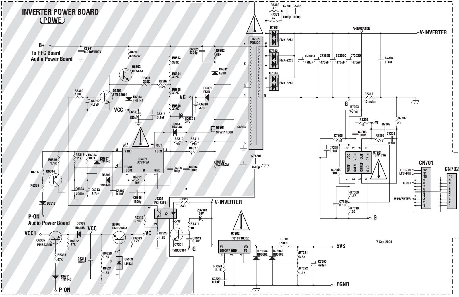
Service mode alignments - SMPS [Power Supply Regulator board] schematic - Thomson LCD12B2
Factory AlignmentThe MT62 chassis is designed for European LCD TV. The main chip is from Mediatec (MTK5362 series) and supports below inputs:
* one analog and digital mixed RF (PAL B/G D/K I, SECAM B/G D/K L/L’,DVB-T)
* one Side AV(CVBS )
* one SCART (CVBS & RGB)
* one SCART (CVBS & YC)
* one CMP (YPrPb can support from 480i up to 1080p)
* one VGA
* three HDMI (can support 480i/p, 576i/p, 720p up to 1080i/p) compliant v1.2. With HDCP, audio included as EIA-861B standard
* one Headphone output
* one SPDIF output
Preconditions – DC/DC Check
Before Power On the chassis, please check and make sure that U811,U9,U31, U7, U6, U11, U5,U4,U34,C74(positive) , C62(positive) , C76(positive) , C152(positive) , C89(positive) , C82(positive) outputs are not shorted to ground.
Supply voltage to P19 and test the relative voltage.
Supply P19 : Pin5,6,8=12v (24v work with IPB PSU);Pin11,12=5v;Pin1,2=Voltage for sound Amplifier IC (18V for 46/52 inch;12V for other inch )
Panel ID check and modify
There is different ID stored in the NVM depended on different Panels. The correct number should be checked in factory menu and if not correct according to the panel list , should be correct manually. The simple way is that select the correct Id in factory menu and restart the set. If the wrong ID make the set display nothing, it must be correct with Hyper terminal.
Once the boards (chassis, KB, IR, PSU…) and the panel are well interconnected, connect all external generator devices to relevant inputs/outputs below according to their respective test patterns format and check picture content and sound quality accordingly.
Audio tones can be defined by the factory (ie: 1KHz & 3KHz, sweep, …).
Picture video formats can be changed by the factory according to their own standard.
ADC Calibration
To ensure the ADC performance, the error of “generator+cable” must be less than 2%. Three inputs require an ADC calibration for the time being, They are:
ƒ VGA
Provide a test signal 1024×768@60Hz with White-black squares.
Select the corresponding “Auto Color” in “ADC Calibration” sub-menu of “Factory Menu”, then press ”OK” to start. Value of status will change to “ALL” if succeed.
CMP:
TestAlignmentSpecification
for TCL-MT5362-V0.50.doc
Provide
a test signal 576i@50Hz with 100% 8 steps ColorBar.
Select the corresponding “Auto Color” in “ADC Calibration” sub-menu of “FactoryMenu”, then press ”OK” to start. Value of status wil change to “ALL” if succeed. Scart RGB
Provide a test signal 100% 8 steps ColorBar.
Select the corresponding “Auto Color” in “ADC Calibration” sub-menu of “FactoryMenu”, then press ”OK” to start. Value of status will change to “ALL” if succeed.
DDC
& EDID Test
The E-EDID data structure are according to VESA Enhanced EDID 1.3 (and EIA/CEA-861B for HDMI).
Both VGA and HDMI have their own separate bin files:
For EDID check, it’s needed to check whether the correct EDID is downloaded by checking corresponding EDID NVM Checksum or read them out to check bit by bit if it is in line with the released EDID bin file.
HDCP Test
For HDCP compliancy, it’s needed to check whether the HDCP key has been well set.
Entering to “Factory Menu” [Service Mode]
To enter into Factory Menu in case of “FactoryKey” is disabled, please to follow below steps:
- press Remote Control key “MENU” to display main menu
- press the subsequent Remote Control keys “7”, “9”, “1” and “5”
The main menu will display”FACTORY” at the last item.
To pop-up Factory Menu in case of “Factory Key” is enabled, please to follow below step:
- press Remote Control key “Blue”
To enable/disable “Factory Key”, follow below steps:
- press Remote Control “OK”key to enter into “System” sub-menu
- press Remote Control “RIGHT”or “LEFT” key till “Factory Key” item
- press Remote Control “Menu”key to toggle mode
To exit “Factory Menu”, press “Exit” key from Remote Control.
To comeback to “Factory Menu” root when you are into a sub-menu:
- press Remote Control “Menu” key.
Entering
to “P” Mode
Turned on the factory key to enter into “P” mode.The TV will display “P” in bottom left corner in “P” mode.
Turned on the factory key to enter into “P” mode.The TV will display “P” in bottom left corner in “P” mode.
Serial
Command Protocol for MTKxx”
A
serial protocol for driving MTK µchip through external +3.3VDC serial device
(USB or COMx) is available. It may facilitate manufacturing process.
1. Both P201 connector from chassis board or either VGA input can also be used
using pin12 (RXD) & pin15 (TXD) just taking care that “Factory Key” from
Factory Menu is enabled.
2. The required serial port settings are as below
* 115200 bps
* 8 data bit
* 1 bit stop
* none parity
3. The command format is like hereafter described into BNS representation:
* 0xBB + Command + Data[[..] + ..] + 0xEE
Both 0xBB and 0xEE bytes are mandatory and used as header and footer of the transmitted frame. Apart from INIT frame that is described further, all sent bytes need to be triggered before by an additional one as 0x50. So a complete frame might match following one:
* 0x50+0xBB+0x50+Command+0x50+Data[[..]+0x50+..]+0x50+0xEE
4. At first time, it might be required to initialize MTK µchip by using once below INIT command (without any triggering byte):
* 0x02 + 0x00 + 0x00 + 0x13 + 0x01 + 0x00
5. A none exhaustive list of commands is already available.
Error link! In invalid.
Modify panel ID with Hyper terminal
1. Connect the PC to the mainboard using an external +3.3VDC serial device (USB or COMx) on P9 or P18 connector from chassis board.
2. Provide the voltage on P19 connector (Pin5,6,8=12v;Pin11,12=5v) from chassis board
3.Save the password file “password for hyperTerminal.txt” to your computer.

4. Start HyperTerminal “HyperTrm.exe” in your computer.
5. Fill the name.
6. Select the Com Port you are using.
7. Set the items as below picture.

Select
“File >Save >” to Save the setting. Then start HyperTerminal “atsc.ht” in
your computer instead of step 3 to 7 later.
8. Send the password.
9. Select the password file saved in your computer.
10. Under the folder “DTV>” enter “pmx.s.p +ID”,e.g.: pmx.s.p 102
See the panel ID in another document <Panel list for MT62>.
See the panel ID in another document <Panel list for MT62>.
Press
“Enter”, the panel signal will be printed in the window.

SMPS circuit diagram [Schematic] [Click on the pictures to zoom in]