
If a “jam” is found, the defective part must be located and
rectified by the following procedures.
The paper path can be divided into two sections: 1) paper
pickup and feed block, and 2) fixing and delivery block.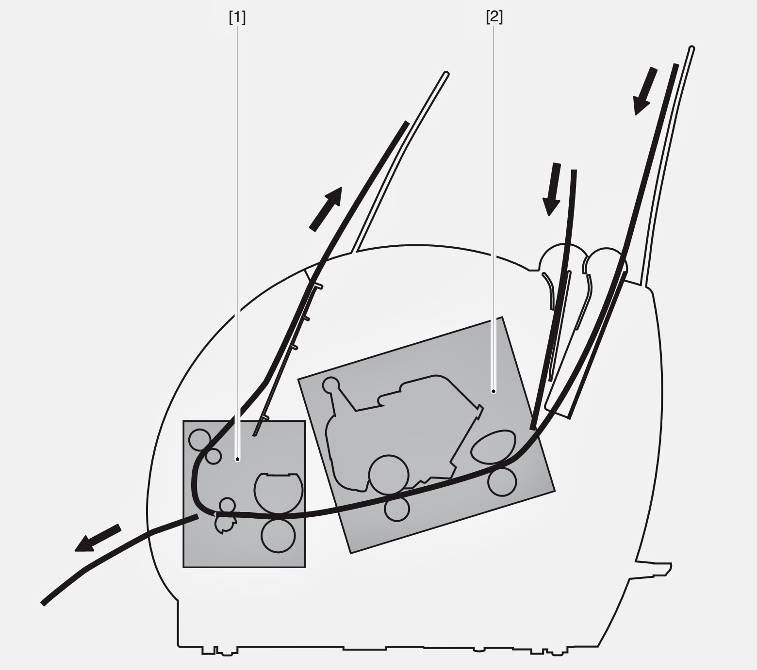
Paper Pickup Unit
- The paper top sensing lever does not move smoothly or is damaged. à If the lever is not installed properly, reinstall it correctly. If the lever is damaged or deformed, replace it.
- Defective paper top sensing lever spring. à If the spring is out of place, set it in the right position. If the spring is deformed or damaged, replace it.
- Worn, deformed or dirty pickup roller or feed roller. à Clean the rollers if dirty. If the rollers are worn or deformed, replace them.
- Defective lifting plate spring. à If the spring is out of place, set it in the right position. If the spring is deformed or damaged, replace it.
- Poor contact in the connectors on the main motor drive signal line. à Reconnect the connector J007F on the main motor.
- Poor contact in the connectors on the pickup roller solenoid drive signal line. à Reconnect the connector J204F on the engine controller PCB.
- Defective pickup roller solenoid. à Disconnect the connector J204F on the engine controller PCB. Measure the resistance between the connector J204-1 and J204-2 on the cable side. If the measured value is not about 120Ω, replace the pickup roller solenoid.
- Defective paper top sensor. à Replace the paper top sensor.
- Defective main motor. à Replace the main motor.
- Defective engine controller PCB. à Replace the engine controller PCB.
- Defective deflector. à If the deflector is worn, broken, nicked or damaged, replace it.
- Dirty or scarred fixing unit entrance guide or toner build-up on the guide. à Clean the guide if dirty. Replace the guide if the dirt cannot be removed.
- The pressure (nip width) of the pressure roller is not within the specification. à Replace the fixing pressure units.
- The pressure roller does not rotate smoothly. à Check whether the gear is worn or damaged. If the pressure roller is worn, replace it.
- Deformed or damaged fixing film unit and pressure roller. à If the fixing film unit and pressure roller are deformed or damaged, replace them.
- The paper delivery-sensing lever does not move smoothly or is damaged. à Adjust the lever to move smoothly. Replace the lever if damaged.
- Defective paper delivery sensing lever spring. à If the spring is out of place, set it in the right position. Replace the spring if damaged or deformed.
- The fixing delivery roller does not rotate smoothly. à Check the gears, and replace any worn or fractured gear(s). If the fixing delivery roller is worn, replace it.
- The facedown delivery roller does not rotate smoothly. à Check the gears, and replace any worn or fractured gear(s). If the facedown delivery roller is worn, replace it.
- Defective engine controller PCB. à Replace the engine controller PCB.
Multiple Feed
- Worn or dirty separation pad surface. à Clean the separation pad surface if dirty. Replace the separation pad if worn.
- Defective separation pad spring. à If the spring is out of position, set it in the right position. Replace the spring if deformed.
- Worn or dirty sub pad surface. à Clean the sub pad surface if dirty. Replace the sub pad if worn.
- Paper dust or dirt accumulates on the pickup roller, feed roller, and paper guide. à Clean the dirty areas.
- Dirty fixing unit entrance guide and pressure roller. à Clean the fixing unit entrance guide and pressure roller.
- Scarred or deformed fixing film unit. à Replace the unit if scarred or deformed.
- Scarred or deformed paper guide. à Check the paper path. Replace any scarred or deformed guide(s).
- Paper dust or dirt accumulates on the pickup roller, feed roller, and paper guide. Clean the dirty areas.
- Scarred or deformed feed roller. Replace the roller if scarred or deformed.
- Scarred or deformed paper guide. Check the paper path. Replace any scarred or deformed guide(s)
- Blown fuse (FU101). à Referring to VII-C-a in Chapter 3, replace the fuse (FU101).
- Defective engine controller PCB. à Replace the engine controller PCB.
- No AC power is supplied. à Perform the “No AC Power” checks.
- Overcurrent/overvoltage detection circuit is activated.
- If the problem persists after the power supply connector is plugged OFF and then IN again, find the cause of activation of the overcurrent/overvoltage detection circuit in the power supply unit. Wait for two minutes or more before turning the power back ON.
- Blown fuse (FU102). à Referring to VII-C-a in Chapter 3, replace the fuse (FU102).
- Defective engine controller PCB. à Replace the engine controller PCB.
- The laser shutter cannot be opened due to the damaged claw of the cartridge cover. à Replace the cartridge cover.
- Poor contact in the connectors in the laser scanner unit. à Reconnect the connector J801F, J802F on the laser/scanner unit and connector J208F on the engine controller PCB.
- Defective laser/scanner unit. à Turn ON the printer. Immediately after turning ON the printer, if the voltage between the connectors J208M-5 and J208M-6 on the engine controller PCB is about +5V and also the voltage between the connectors J208M-1 and J208M-4 is about +24V, replace the laser/scanner unit.
- Defective engine controller PCB. à Replace the engine controller PCB.
- Poor contact in the connectors.à Reconnect the connector J206 on the engine controller PCB.
- Broken wire or short-circuited thermistor. à Turn OFF the power and remove the fixing unit from the printer. Measure the resistance between the connectors J703-1 and J703-2 on the fixing unit side. If the resistance is not within the range from about 250 kΩto about 800 kΩ(room temperature), replace the fixing film unit.
- Broken wire of the heater or blown thermal fuse. à Remove the fixing unit. Check the connectors J102F-1 and J102F-2 on the fixing unit side for continuity. If the connectors have no continuity between them, replace the fixing film unit.
- Defective engine controller PCB.à Replace the engine controller PCB.
- Defective paper delivery sensor spring. à If the spring is not installed correctly, reinstall it correctly. Or, if the spring is deformed or damaged, replace it.
- Defective paper delivery sensing lever. à If the lever is not installed correctly, reinstall it correctly. Or, if the lever is deformed or damaged, replace it.
- Defective paper top sensor spring. à If the spring is not installed correctly, reinstall it correctly. Or, if the spring is deformed or damaged, replace it.
- Defective paper top sensing lever. à If the lever is not installed correctly, reinstall it correctly. Or, if the lever is deformed or damaged, replace it.
- Defective engine controller PCB. à Replace the engine controller PCB.
- Damaged claw of the door switch on the connector holder. à Action: Replace the connector holder.
- Defective door open detection unit. à Replace the door open detection unit.
- Defective door open detection switch / engine controller PCB. à Replace the engine controller PCB.
- Defective paper out sensing lever. à Action: If the lever is not installed correctly, reinstall it correctly. Or, if the lever is deformed or damaged, replace it.
- Defective paper out sensor. à Action: Replace the paper out sensor (PS003.)
- Defective engine controller PCB. à Replace the engine controller PCB.
- Poor contact in the primary high-voltage contact on the engine controller PCB and cartridge contact. à Clean the contacts if dirty. If the problem still remains after cleaning, or parts are deformed or damaged, replace them.
- Defective cartridge. à Replace the cartridge.
- Defective engine controller PCB. à Replace the engine controller PCB.
Checking the Nip Width of the Pressure Roller. The fixing unit is not designed to allow the
adjustment of the pressure (nip width); however, the incorrect nip width can cause
fixing problems. Follow the procedures below to check the nip width:
- Make an all-black print of A4 size using an EP-22 cartridge, and bring the print to the customer’s site.
- Place the all-black print in the multi-purpose tray of the printer, with the printed side facing down.
- Select face up delivery by turning the delivery switching lever down.
- Press on the test print switch.
- Turn OFF the printer when the leading edge of the print emerges at the faceup tray. After 10 seconds from tuning OFF the printer, open the cartridge cover and take out the print.
- Measure the width of the glossy band across the paper and check that it meets the requirements as shown in Table.

CLICK ON THE PIRCURES TO ZOOM
This printer’s electrical system does not require
adjustment.