
SERVICE POSITION
For easy servicing of a TV set, the
set should be put face down on a soft flat surface, foam buffers or other
specific workshop tools. Ensure that a stable situation is created to perform measurements
and alignments. When using foam bars take care that these always support the
cabinet and never only the display.
Caution: Failure to follow these
guidelines can seriously damage the display.
Ensure that ESD safe measures are taken.ASSEMBLY / PANEL REMOVAL [THRILLER STYLING]
Instructions below apply to the 32PFL3606H/12, but will be similar for other models.
- Disconnect the mains power cord before removing the rear cover.
- Remove fixation screws that secure the base assembly, pull out the base assembly from the set.
- Then remove the fixation screws that secure the rear cover.
- Lift the rear cover from the TV. Make sure that wires and flat foils are not damaged while lifting the rear cover from the set.

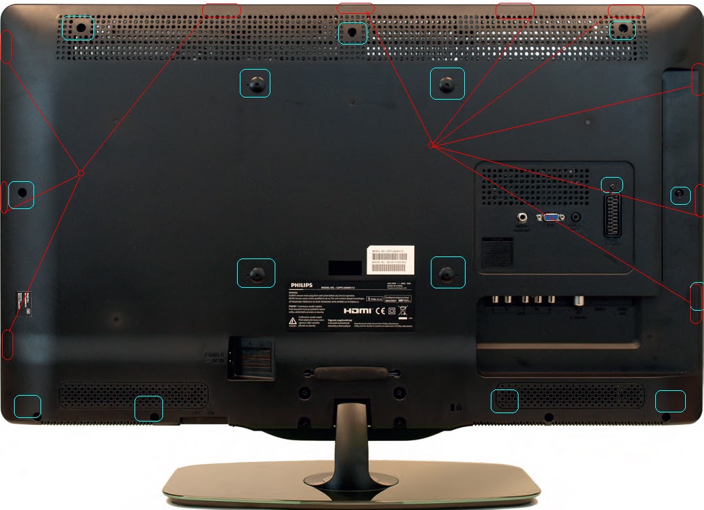
ASSEMBLY / PANEL REMOVAL [BERLINALE STYLING]
Instructions below apply to the
32PFL5606H/12, but will be similar for other models.
- Disconnect the mains power cord before removing the rear cover.
- Remove screw caps that cover VESA screw holes.
- Remove all fixation screws that secure the rear cover. At the indicated areas the cover is secured by clips. Be very careful with releasing those.
- Lift the rear cover from the TV. Make sure that wires and flat foils are not damaged while lifting the rear cover from the set.
SSB [Small Signal Board] Removal.
Caution: it is mandatory to remount all
different screws at their original position during re-assembly. Failure to do
so may result in damaging the SSB.
- Release the clips from both the LVDS Flat Foil connectors that connect with the SSB. Caution: be careful, as these are very fragile connectors. Take the flat foils out of their connectors.
- Release the clamps and unplug all other connectors.
- Remove the fixation screw from the clamp near the bottom of the SSB, and take the clamp out.
- Release the tape near the bottom side of the set from the LCD panel.
- Remove all other fixation screws from the SSB.
- Take out the SSB together with its shielding.
- Remove the screw near the L/R audio connectors.
- The SSB can now be shifted from the side connector cover, then lifted and taken out of the shielding.
19080_103_110302.eps
110404
19080_104_110308.eps
110404

No comments:
Post a Comment