
If you are replacing a flapper valve on the bottom side of
the valve plate (side facing the compressor housing), remove the flapper valve
screw (1) with a 1/4" hex socket, lift off the valve keeper strip (2), clean
any debris with a soft, damp cloth. Turn the compressor head upside down and
place the valve plate on the compressor head and orient it as illustrated. Note
the position of the valve ports and the location of the power leads on the compressor
housing.
Orient a flapper valve (1) over Port 2. Observe the location
of the notches (2) at the end of the flapper valve.
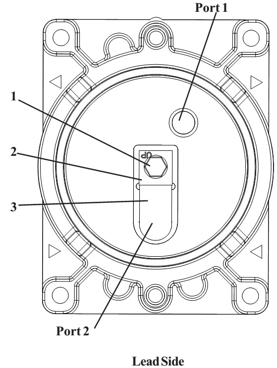

- Place a valve keeper strip (3) over the flapper valve, observing that the word “UP” is facing you, not the valve plate, and oriented as shown in the illustration.
- Line up the screw holes in all of the valve components and insert the flapper valve screw (4) into the valve plate.
- Make sure the flapper valve is centered over the Port and that the valve keeper strip lines up with the flapper valve.
- Do not over tighten the flapper valve screw or it will shear off in the valve plate.
- Tighten the flapper valve screw to 18 inch pounds, using a torque wrench with a 1/4" hex socket attachment.

- Carefully remove the fan by pulling it straight off the motor shaft. Do not pull the fan blades.
- Turn the motor shaft to align the eccentric set screw with its access hole and use an Allen wrench to loosen the eccentric set screw (see illustration for location of access hole).


- Make sure the connecting rod is at "Top Dead Center". Slide the connecting rod assembly straight off the shaft through the opening in the Housing.

Rebuilding Connecting Rod Assemblies. If you are rebuilding the connecting rod assembly
using component parts, follow this procedure:
When replacing the piston cup (4), be sure to replace the
sleeve (1) at the same time. Place the
con rod shaft in a fixture before attempting to remove the retainer screw. Heat will help to dissolve the lactate bond.
- Remove the retainer screw (2) from the cup retainer.
- Remove the retainer (3) from the connecting rod.
- Remove the cup (4) and discard.
- Place the new piston cup (4) on the connecting rod.
- Place a piston cup retainer (3) on the cup/connecting rod making sure the boss of the retainer is seated in the pilot of the rod.
- Insert the retainer screw (2) into the connecting rod (5) and tighten to 95-105 inch-pounds.

Assembly of the Connecting Rod to the Compressor.
- Line up eccentric set screw with flat on shaft. Slide connecting rod assembly over shaft through front of housing with eccentric toward end of shaft. Push connecting rod assembly tight against housing bearing.
- Rotate eccentric to line up setscrew with access hole in bottom of housing. Tighten screw to 125 in. lbs. Make sure the eccentric set screw is seated perpendicular on the shaft flat.


After the connecting rod assembly and eccentric are
correctly assembled, you can assemble the valve plates and head to the
compressor.
To prevent damage to the compressor, never apply any sealant
or lubrication to the O-rings.
- Insert a new head gasket O-ring into the groove located on the top of the valve plate.
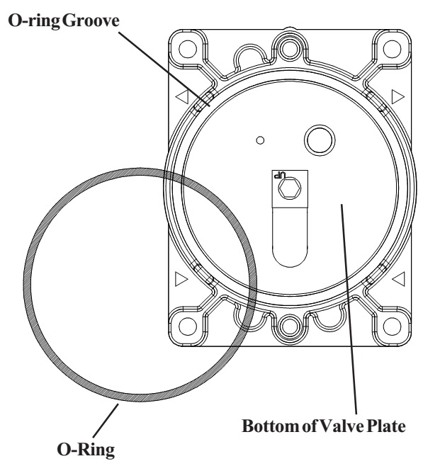
- Insert the valve plate gasket O-ring into the O ring groove located on the bottom of the valve plate.

- Position the compressor housing as shown in the illustration. Notice the orientation of the power leads.
- Observe the orientation of the valve plate assemblies. The tabs on the valve plate indicate exhaust side. Place them on the compressor housing as shown.
Ensure that O-Rings are fully assembled in grooves and not
pinched.
Make sure that the connecting rod sleeves are seated against
the compressor housing.


- Place the head on the valve plate assemblies observing the position of the air intake and exhaust ports.
- Insert the head screws and finger tighten each screw until it is snug. Use a Torx® T-25 driver to tighten each head screw to 55 inchpounds, in the sequence shown.

Servicing the Fan
If one or both of the fans break, use the following procedure:
- Carefully remove the fan by pulling it straight off the motor shaft.
- Align the flat on the motor shaft with the flat on the fan and slide the fan back onto the motor shaft, making sure the fan clip (1) faces as shown.
