
In this product the single voltage (3.3V) is used for the regulator.
The reference voltage is the REFO1 (1.65V) instead of the GND. If you should mistakenly short the REFO1
with the GND during adjustment,
accurate voltage will not be obtained, and the servo’s disoperation will apply
excessive shock to the pickup. To avoid such problems:
- Do not mix up the REFO1 with the GND when connecting the (-) probe of measuring instruments. Especially on an oscilloscope, avoid connecting the (-) probe for CH1 to the GND.
- In many cases, measuring instruments have the same potential as that for the (-) probe. Be sure to set the measuring instruments to the floating state.
- If you have mistakenly connected the REFO1 to the GND, turn off the regulator or the power immediately.
- Before mounting and removing filters or leads for adjustment, be sure to turn off the regulator.
- For stable circuit operation, keep the mechanism operating for about one minute or more after the regulator is turned on.
- In the test mode, any software protections will not work. Avoid applying any mechanical or electrical shock to the mechanism during adjustment.
- The RFI and RFO signals with a wide frequency range are easy to oscillate. When observing the signals, insert a resistor of 1k ohms in series.
- The load and eject operation is not guarantied with the mechanism upside down. If the mechanism is blocked due to mistaken eject operation, reset the product or turn off and on the ACC to restore it.
TEST MODE
This mode is used to adjust the CD mechanism module.
To enter the test mode.
While pressing the 4 and 6 keys at the same time, reset.
To exit from the test mode.
Turn off the ACC and back up.
- During ejection, do not press any other keys than the EJECT key until the loaded disc is ejected.
- If you have pressed the (à) key or (ß) key during focus search, turn off the power immediately to protect the actuator from damage caused by the lens stuck.
- For the TR jump modes except 100TR, the track jump operation will continue even if the key is released.
- For the CRG move and 100TR jump modes, the tracking loop will be closed at the same time when the key is released.
- When the power is turned off and on, the jump mode is reset to the single TR (91), the RF amp gain is set to 0dB, and the auto-adjustment values are reset to the default settings.
CHECKING THE GRATING AFTER CHANGING THE PICKUP UNIT
The grating angle of the PU unit cannot be adjusted
after the PU unit is changed. The PU unit in the CD mechanism module is
adjusted on the production line to match the CD mechanism module and is thus
the best adjusted PU unit for the CD mechanism module. Changing the PU unit is
thus best considered as a last resort. However, if the PU unit must be changed,
the grating should be checked using the procedure below.
Method :
Measuring Equipment àOscilloscope, Two L.P.F.
Measuring Points à E, F, REFO1
Disc > TCD-782
Mode > TEST MODE

- In test mode, load the disc and switch the 3V regulator on.
- Using the àand ß buttons, move the PU unit to the innermost track.
- Press key 3 to close focus, the display should read "91". Press key 2 to implement the tracking balance adjustment the display should now read "81". Press key 3. The display will change, returning to "81" on the fourth press.
- As shown in the diagram above, monitor the LPF outputs using the oscilloscope and check that the phase difference is within 75°.
- If the phase difference is determined to be greater than 75°try changing the PU unit to see if there is any improvement. If, after trying this a number of times, the grating angle does not become less than 75°then the mechanism should be judged to be at fault.
Because of eccentricity in the disc and a slight
misalignment of the clamping center the grating waveform may be seen to
"wobble" ( the phase difference changes as the disc rotates). The
angle specified above indicates the average angle.
Reloading the disc changes the clamp position and may
decrease the "wobble".
ERROR MODE
Error is displayed with number for Error cause when CD is
inoperative or stops with Error during operation. The purpose is to reduce nonsense calls from users as well as to
assist all related analysis and repair for defects at service station.
When CSMOD (CD mode area for system) is SERRORM, Error code
will be written in DMIN (minutes area for display), DSEC (seconds area for display). The same data shall be
written in DMIN and DSEC. DTNO is blank as usual.
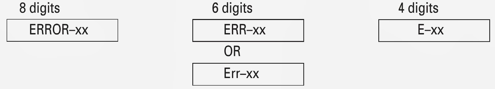
The following is about LCD display ability. xx is Error
number.
{Click on the pictures to Zoom}
ERROR CODE LIST
Error doesn’t display in mechanism only. (CD off causes
mechanism off)
If TOC can’t be read, error wouldn’t occur, but mechanism
still continues its operation.
The upper digits of
error code is mainly classified by 3 kinds as follows: 1x: Setup related error, 3x: Search related
error, Ax: Other errors.

In the normal operation mode (with the detachable panel
installed, the ACC switched ON, the standby mode cancelled), shift the TEST IN
(Pin 86) terminal to H.
The clock signal is output from the PCL terminal (Pin 37).
The frequency of the clock signal is 312.5kHz that is one
32th of the fundamental frequency.
The clock signal should be 312.5kHz.
If the clock signal is out of the range, the X'tal (X601)
should be replaced with new one.