
The chassis in the HDLP50W151 is made up of seven (7) major
modules. These include the “AC In” CBA that
contains the Standby and Run power supplies. The “Audio” CBA, which processes
all audio signals. The “A/V In/Out” CBA has the in/out jacks and also does all
the video and audio switching. The fourth is the “Formatter” circuit board and
it is responsible for converting the video signals into a format that the light
engine can use. The fifth is the “DM2CR” which contains the ATSC tuner, NTSC
tuner and the QAM digital cable decoder. The DM2CR also serves as the system
control for the instrument. The sixth module is the light engine and seven is the lamp power supply.
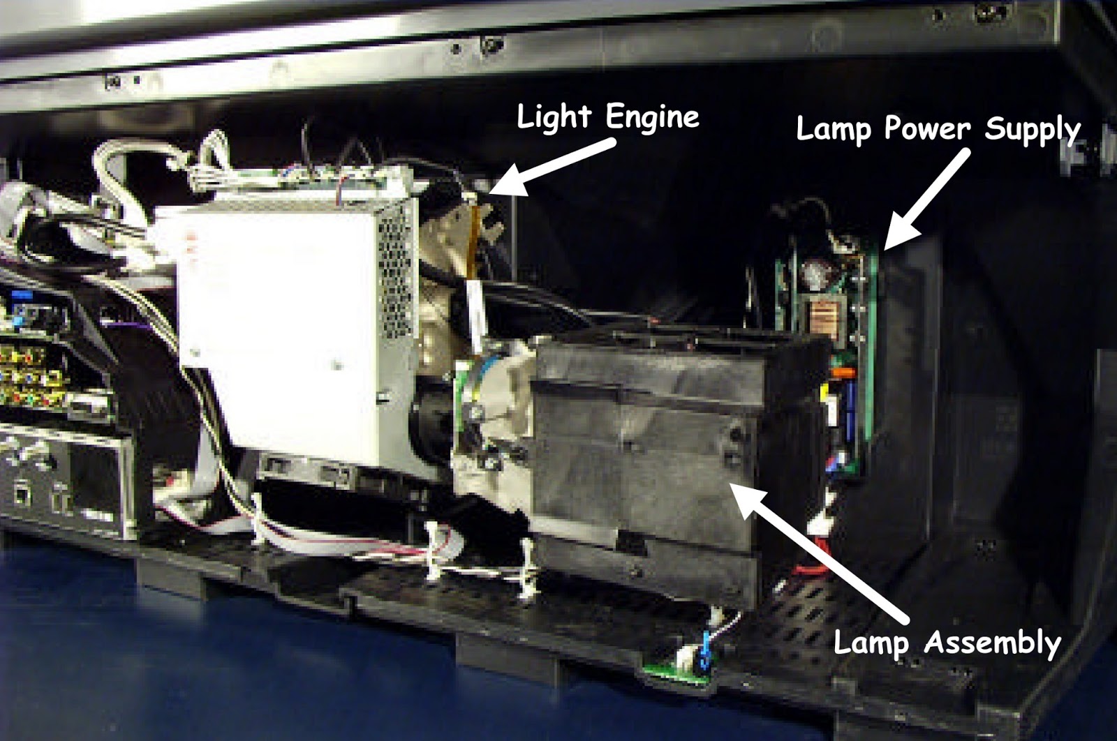
LIGHT ENGINE ASSEMBLY

CHASSIS OVERVIEW
There are five (5) major circuit boards in the HDLP50W151
chassis (minus the light engine). These include the “AC In” CBA, “Audio”
processing CBA, the “DM2CR”, the “A/V In/Out” CBA and the “Formatter” CBA.
The AC In CBA provides the Standby DC power and the Run
supply DC power. Both power supplies
are switch mode power supplies and are very similar.
The main difference is that the run supply has an on/off
circuit that is controlled by the system control micro in the DM2CR.
An AC doubler on the AC In CBA is used to generate power for
the lamp power supply.
A valuable troubleshooting tip is to listen for the lamp
power supply relay click when AC is plugged in. Since the relay is power by the
+12VS source, if the relay doesn't click this is a good indication the standby
power supply is inoperative.
The Audio CBA is responsible for final processing of all
base band audio signals. This includes volume, equalization, balance and
Surround Sound. The audio output power amplifiers that drive the internal speakers
are also located on the Audio CBA. Audio for the audio out jacks as well as the
FAV (Front Audio Video) circuit are supplied by the Audio CBA. Power (+/-21V) for the Audio CBA is provided
by the standby supply.
The DM2CR module contains an NTSC and ATSC tuner section as
well as the NTSC PIP tuner. The tuners are capable of processing both digital
and analog RF signals (ATSC & NTSC) from either terrestrial or cable sources.
The DM2CR is also 256QAM digital cable compatible. The DM2CR has 2 DTV Link connectors which are a compressed
digital video inputs offering an IEEE-1394 type video connection for consumer
devices such as satellite receivers, cable receivers, and digital recorders
that meet the CEA specifications for DTV Link. DTV Link is better known as 1394
or FireWire for digital televisions. Audio and video information is carried on
a single wire.
The DM2CR module performs the NTSC decoding of component,
SVHS, and composite video signals. The DM2CR also recovers the teletext, closed
caption and GemStar data signals that accompany any input video.
All 1H video inputs (NTSC) including signals from the A/V
In/Out circuit board are up-converted to 2H by the DM2CR. The video output to
the formatter CBA
is YPrPb component. Any 2H component (YPrPb) that is input
to the A/V In/Out CBA is routed directly to the formatter.
The audio and video in/out jacks are located on the A/V
In/Out CBA. The A/V CBA also provides audio and video switching for external
video and audio signals. The auto detected 1H and 2H video signal are routed
via the A/V In/Out circuit board. The 1H and 2H NTSC is routed to the DM2CR for
up-conversion. Any 2H component external video signal is routed directly to the
formatter circuit for final processing.
The formatter circuit board is responsible for converting
the analog video from either the DM2CR or the analog inputs from the A/V In/Out
circuit board into a format that is compatible with the light engine. All
functions and circuits on the formatter circuit board is monitored and controlled
by the system control
Microcomputer in the DM2CR module. This is accomplished via the RUN 2 I2C clock and data bus. The same I2C bus is also routed through
the formatter board to the light engine. The 2H and 2.14H external video
inputs are applied to the formatter circuit board (via connector BV402) where
it is applied to the BEP (back end processor) for processing into an analog RGB
signal. The NTSC and the ATSC analog
video signal (2H) from the DM2CR is also input to the formatter (via connector BV401).
The video is applied to IV401 for conversion to RGB. The RGB output from IV401
is then applied to the Digital Signal processing circuits where it is digitized
and output to the light engine as DVI (Digital Video Interface).
MMD [DLP] TECHNOLOGY
Texas Instruments Digital Light Processing (DLP) technology
provides an all digital projection display that offers superior picture quality
in terms of resolution, brightness, contrast, and color fidelity. The DLP
device consists of an array of movable mcromirrors. Each mirror is
independently controllable and is used to modulate reflected light. The mirror
is controlled by loading data into the memory cell located below the mirror.
The data electrostatically controls the mirror’s tilt angle which controls whether passes through the
projection lens and onto a screen or reflected away.
Until recently, light-valve technologies for projection
display applications have been unable to take full advantage of the economies
and stability offered by the digital revolution. Increasing digital content has
been incorporated into the transmission and signal processing chain from source
material to the projection display light valve. Ultimately, however, the light
valve itself is analog in nature and subject to analog limitations. The possibility of an
all-digital (source-to-eye) display was realized in 1987 with the invention of the DLP device
at Texas Instruments. The DMD is an
array of fast digital micromirrors, monolithically integrated onto and
controlled by a memory chip.
Digital Light Processing (DLP) systems present
bright, seamless images to the eye, with the characteristics that we have come
to expect from digital technology, namely high image fidelity and stability.
DLP-based displays exhibit no lag or smearing of the image from one digital
frame to the next. The first DLP-based projection display products were
introduced to the market in April 1996.
DISPLAY OPERATION
Each digital light switch of the DMD is an aluminum micromirror,
16 micrometer square, that can reflect light in one of two directions, depending
on the state of an underlying memory cell. The mirror is rotated by electrostatic
attraction produced by voltage differences developed across an air gap between
the mirror and the memory cell. The mirror rotation is limited by
mechanical stops to ±10 degrees. With
the DLP cell in the on state, the mirror rotates to +10 degrees. With the DLP cell in the off state, the mirror
rotates 10 degrees.
DLP DEVICE

DLP CELL TECHNOLOGY

When we combine the DLP device with a suitable light source
and projection optics, the mirror reflects incident light either into or out of
the projection lens by a simple beam-steering action. Thus, the on state of the
mirror appears bright and the off state of the mirror appears dark. The fast
switching time of the mirrors enables the use of a pulse width modulation
technique for the production of gray scale. The DLP device accepts electrical
words representing gray levels of brightness at its input and then outputs digital
light as optical words to the eye. Because
of the short pulse duration, the optical words are interpreted by the eye of the observer as analog light containing up to
one billion or more color and gray scale combinations per pixel. Furthermore,
the fast switching time results in a lag free image. Digital light is accurate
because the light pulse durations are determined by the precise division of
time. The resulting projected image faithfully reproduces the original source
material and the image is stable, independent of temperature or age of the
projector, and is free from photo degradation effects, even up to brightness
levels necessary for electronic cinema. The tiny gaps between the mirrors
diminish objectionable pixilation effects and create a seamless image that has
long been the hallmark of DMD-based projection displays.