
Contn:
[3]
DISPLAY ASSEMBLY
- Close the computer.
- Turn the computer upside down with the rear panel toward you.
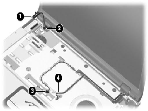
- Make note of which wireless antenna cable is attached to which antenna clip on the Mini Card module before disconnecting the cables. Then disconnect the cables from the module.
- Remove the two Phillips PM2.5×7.0 screws that secure the display assembly to the computer.

- Turn the computer display-side up with the front toward you.
- Open the computer to an upright position.
- Disconnect the following cables:
- Display cable.
- Microphone cable.
- Camera cable.
- Remove the wireless antenna cables from the routing channels in the top cover.
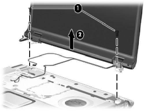
- Support the display assembly when removing the following screws. Failure to support the display assembly can result in damage to the display assembly and other computer components.
- Remove the two Phillips PM2.5×7.0 screws that secure the display assembly to the computer.
- Remove the display assembly.
- Remove the following:
- Four rubber screw covers on the display bezel top edge.
- Two rubber screw covers on the display bezel bottom edge.
- Four Phillips PM2.5×5.0 screws on the display bezel top edge.
- Two Phillips PM2.5×7.0 screws on the display bezel bottom edge.
- The display rubber screw covers are included in the Display Screw Kit, spare part number 431399-001.

- Flex the inside edges of the left and right sides and the top and bottom sides of the display bezel until the bezel disengages from the display enclosure.
- Remove the display bezel.

- Remove the camera module rom the display enclosure.
- Disconnect the camera cable from the camera module.

- Remove the inverter from the display enclosure.
- Disconnect the display cable and the backlight cable from the display inverter.

- Remove the four Phillips PM2.5×5.0 screws that secure the display panel to the display enclosure.
- Remove the display panel.

- Slide the left and right display hinge covers off of the display hinges.
- Remove the two Phillips PM2.0×3.0 screws that secure each hinge to the display enclosure.
- Remove the display hinges.

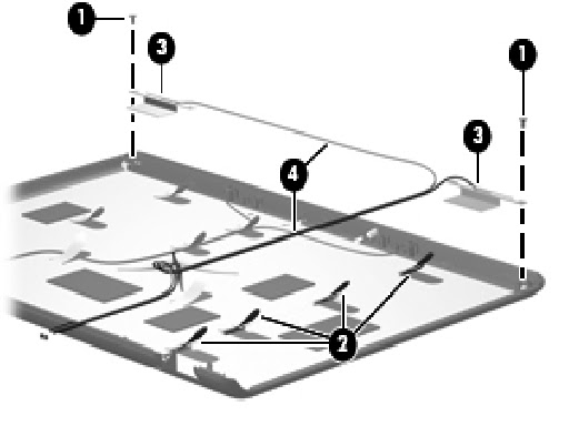
- If it is necessary to replace the wireless antenna transceivers and cables, remove the Phillips PM2.0×4.0 screw that secures each transceiver to the display enclosure.
- Remove the wireless antenna cables from the clips built into the display enclosure.
- Detach the wireless antenna transceivers from the display enclosure.
- Remove the wireless antenna cables.
- If it is necessary to replace the microphones and cables, release the retention tabs built into the display enclosure that secure the microphone cables to the display enclosure.
- Remove the microphone receivers from the clips in the display enclosure.
- Remove the microphone cables from the display enclosure.

- If it is necessary to replace the camera cable, release the retention tabs built into the display enclosure that secure the camera cable to the display enclosure.
- Remove the camera cable from the display enclosure.
