
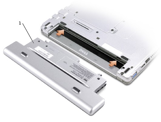
BATTERY REMOVING AND REPLACEMENT.
- Ensure that the computer is turned off, suspended in a power management mode, or connected to an electrical outlet.
- If the computer is connected to a media base (docked), undock it. See the documentation that came with your media base for instructions.
- Slide the battery latch releases on the bottom of the computer and remove the battery from the bay.

- To install the battery, slide the battery or the optional extended battery into the bay until the latch release clicks.
ADDING MEMORY
- Ensure that the work surface is flat and clean to prevent scratching the computer cover.
- Save and close any open files, exit any open programs, and shut down the computer.
- If the computer is connected to the media base (docked), undock it.
- Disconnect the computer from the electrical outlet.
- Wait 10 to 20 seconds, and then disconnect any attached devices.
- Remove any installed PC Cards and battery.
- Turn the computer over, unscrew both captive screw(s) from the memory module/Mini PCI/modem cover, and remove the cover.
- If you are replacing a memory module, remove the existing module.
- Handle components and cards by their edges, and avoid touching pins and contacts. Ground yourself by touching a metal connector on the back of the computer. Continue to ground yourself periodically during this procedure.
- Use your fingertips to carefully spread apart the securing clips on each end of the memory module connector until the module pops up.

- Remove the module from the connector

- Ground yourself and install the new memory module.
- Align the notch in the module edge connector with the tab in the center of the connector slot.
- Slide the module firmly into the slot at a 45-degree angle, and rotate the module down until it clicks into place. If you do not hear the click, remove the module and re-install it.
- If the memory module is not installed properly, the computer may not boot properly. No error message indicates this failure.

## If
the cover is difficult to close, remove the module and re-install it. Forcing the cover to close might damage your
computer.

- Insert the battery into the battery bay, or connect the AC adapter to your computer and an electrical outlet.
- Turn on the computer.
- As the computer boots, it detects the additional memory and automatically updates the system configuration information.
- In the Microsoft® Windows® XP operating system, click the Start button, click Help and Support, and then click Computer Information.
- You can also get this information by right-click on ‘My Computer’ icon, and click on ‘Properties’.
- In Windows 2000, right-click the My Computer icon on your desktop, and then click the General tab.
MODEM REPLACEMENT
- Ensure that the work surface is flat and clean to prevent scratching the computer cover.
- Save and close any open files, exit any open programs, and then shut down the computer.
- If the computer is connected to a media base (docked), undock it.
- Disconnect the computer from the electrical outlet.
- Wait 10 to 20 seconds and then disconnect any attached devices.
- Remove any installed PC Cards or blanks, battery, and devices.
- Turn the computer over and loosen the two captive screws on the modem cover, and remove the cover.
- Remove the screw securing the modem to the system board, and set it aside.
- Pull straight up on the attached pull-tab to lift the modem out of its connector on the system board, and disconnect the modem cable.
- {Modem => Y0231.}

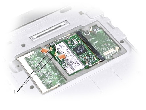
REPLACING A MINI PCI CARD
- Ensure that the work surface is flat and clean to prevent scratching the computer cover.
- Save and close any open files, exit any open programs, and shut down the computer.
- If the computer is connected to a media base (docked), undock it.
- Disconnect the computer from the electrical outlet.
- Wait 10 to 20 seconds and then disconnect any attached devices.
- Remove any installed PC Card or blanks, battery, and devices.
- Turn the computer over, and loosen both the captive screw(s) from the Mini PCI card cover and remove the cover.
- Disconnect the Mini PCI card from the attached cables.
- Release the Mini PCI card by spreading the metal securing tabs until the card pops up slightly.
- Lift the Mini PCI card out of its connector.
- To avoid damaging the Mini PCI card, never place cables on top of or under the card.
- To replace a Mini PCI card, align the card with the connector at a 45-degree angle, and press the Mini PCI card into the connector.
- Lower the Mini PCI card toward the inner tabs to approximately a 20-degree angle.
- Continue lowering the Mini PCI card until it snaps into the inner tabs of the connector

- Lift the mini PCI card out of its connector.

- Do these process in reverse to insert a new PCI card.
KEYBOARD REMOVAL
- Remove the battery.
- Remove the four M2 x 4-mm screws labeled with an arrow from the bottom of the computer.
- Turn the computer over, and insert a ¼-inch flat-blade screwdriver into the slot to the right of the keyboard locator tab.
- Pry up the keyboard locator tab, and the keyboard pops up.
- Pull the keyboard a small distance toward the front of the computer to release the four securing tabs located across the back edge of the keyboard.
- Rotate the keyboard toward the front of the computer and place it face-down on the palm rest.
- Do not pull on the keyboard flex cable.


- Open the ZIF connector on the system board by pulling the ZIF [Zero Insertion Force] connector tabs toward the back of the computer.
- Remove the keyboard flex cable from the ZIF connector.
- Lift the keyboard up and out of the computer.

KEYBOARD REPLACEMENT
- Place the keyboard face-down on the palm rest, with the keyboard flex cable pointing toward the back of the computer.
- To avoid damage to the connector pins, insert the keyboard flex cable evenly into the ZIF connector on the system board, and do not reverse the keyboard flex cable.
- Ensure that the ZIF connector is open by pulling the ZIF connector tabs toward the back of the computer.
- Press the keyboard flex cable into the ZIF connector.
- Close the ZIF connector by pushing the ZIF connector tabs toward the front of the computer. To aid with proper flex cable connection, a locator line has been added near the end of the flex cable. Press the cable into the connector until the line disappears and hold the cable steady while you close the ZIF connector. (The white line may reappear after the connector is closed, which should not indicate a problem with the connection.)
- Position the keyboard flex cable so that it is not pinched when you replace the keyboard in the bottom case.
- Rotate the keyboard back and fit it into the bottom case.
- Ensure that all four keyboard securing tabs are engaged in their respective slots before trying to completely seat the keyboard. Press down on the left and right <Alt> keys to help control tab/slot alignment.
- When the keyboard appears to be completely seated, confirm that the front edge of the keyboard is aligned with the edge of the palm rest before proceeding.
- Replace the four M2 x 4-mm screws on the bottom of the computer.
Contd: