BACK COVER REMOVAL
- Remove AC power from the instrument.
- Remove 17 screws to release the back cover.
- Pull back the cover straight back to remove it.

Note:
With the back off the safety interlock switch will disable the doubler circuit to Lamp Power supply preventing the Lamp from operating. To defeat the interlock switch during servicing short connector J13101 by placing an alligator clip across the pins as shown below. WARNING: Eye damage may result from directly viewing the light produced by the lamp used in this instrument. Ultraviolet radiation eye protection required during servicing.

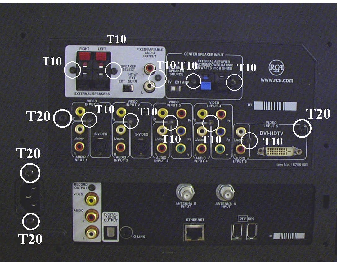
JACK PANEL COVER REMOVAL
- Remove the back cover.
- Remove 4 (40) T20 and 10 (10) T10 screws on the back of the Jack Panel Cover.
- Pull the jack panel cover straight back to remove.
CHASSIS TOWER SERVICE POSITION.
- Remove Lower Back cover.
- Remove Jack Panel cover.
- Pull chassis towards rear. The chassis tower should extent off the back of the chassis tray approximately four inches.
- The tower can be rotated after release to access the cables and wire clips at the front of the plastic frame.
DLP
- P24602 TO AVIN CBA
- P24603 TO AUDIO CBA
- P24604 TO DM2
- P24605 TO DM2

ACIN / POWER SUPPLY REMOVAL
- Remove all cables to ACIN / Power supply CBA.
- Releasing retaining clip on top edge, between OO and PP, and slide the ASIN / Power supply CBA rearward until the plastic tabs on the frame line up with the slots in the CBA.
- Pull ACIN / Power supply CBA away from plastic bracket and lift out of bottom rail.

AUDIO CBA REMOVAL
- Put the Chassis Tower in service position.
- Release cable P11903 from plastic clip at the front of ACIN / Power supply and unbundle the cable to provide slack for removing the CBA.
- Slid audio CBA out of tray.
- Disconnect cables from the back of the Audio CBA.

AVIN CBA REMOVAL
- Remove lower back cover and jack panel cover.
- Disconnect cables from back and right side of AVIN CBA.
- Slide AVIN CBA out.

LIGHT ENGINE REMOVAL [LE]
- Remove back cover.
- Disconnect the ballast connector from the top side of the light engine driver CBA.
- Disconnect the power supply from the top of the LE driver CBA
- Disconnect the DVI connector from the side of the LE driver CBA.
- Disconnect the lamp supply connector from the the side of lamp ass'y.
- Remove 3 screws from around the LE driver enclosure.
- Rotate the LE connector clockwise until the metal ears on the LE ass'y clear the plastic frame tabs. Pull the LE straight back until the lens clears the plastic housing.


SPEAKER GRILL REMOVAL
- Remove 6 screws , three from each side of the lower back.
- From front of the instrument gasp both bottom corners of the speaker grill and pull out and slightly upward to disengage the plastic stays.
- Gasp both top corners of the grill and pull straight out.

KEYBOARD REMOVAL
- Remove speaker grill.
- Disconnect the two KBD cables.
- Push out the plastic rail closest to the grill edge until CBA can be removed.

FRONT AUDIO CBA REMOVAL
- Remove speaker grill.
- Disconnect the FAV cable.
- Push outward on both plastic rails until the CBA can be removed.
IR INTERFACE CBA REMOVAL.
- Remove the speaker grill.
- Disconnect IR cables.
- Remove the screw used to retain the CBA.

SPEAKER ASSEMBLY REMOVAL
- Remove the speaker grill.
- Disconnect speaker cable.
- Remove screw used to secure speaker.
- Pull the ass'y straight forward to remove.

PROTECTIVE SHIELD REMOVAL
- Remove speaker grill.
- Remove screws from both back side edges and top back edge of the cabinet.

- Remove 2 screws from underneath the protective shield frame.

- Lean the top edge of the protective shield forward approximately 12 inches, or until the bottom of the shield is released by the frame and lift and remove.
SCREEN REMOVAL
- Remove the speaker grill.
- Remove the protective shield.
- Slide the screen out to the left, until it clears the upper and lower frame rails.
LARGE MIRROR REMOVAL
- Remove the speaker grill.
- Remove the protective shield.
- Remove the front screen.
- Remove the 10 screws from the sides and bottom of the mirror.
- Caution: The large mirror is made of glass, and care must be taken to support the mirror while removing.

No comments:
Post a Comment