[6]
Contn:
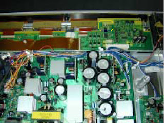
REMOVING THE SAVING POWER: UPPER RIGHT PCB.


Contn:
REMOVING THE SAVING POWER: UPPER RIGHT PCB.
- Remove rear case.
- Remove fan and marked connector.
- Remove the 6 screws and Fan plinth.

- Remove one screw and Saving Power Upper Right PCB.

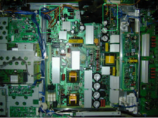
REMOVING THE SAVING POWER: LOWER RIGHT PCB
- Remove rear case.
- Remove two screws.
- Remove the connector.

- Remove one screw and Saving Power Lower Right PCB.

REMOVING THE SAVING POWER: UPPER LEFT PCB
- Remove rear case.
- Remove one screw and Saving Power Upper Left PCB.

REMOVING SAVING POWER LOWER LEFT PCB
- Remove the rear case.
- Remove one screw and Saving Power Lower Left PCB.

REMOVING POWER SUPPLY PCB
- Remove rear case.
- Remove fan.
- Remove 3 screws

- Disconnect the connectors.

- Remove 9 screws and Power Supply PCB.

REMOVING THE DIGITAL PROCESS AND CONTROL PCB
- Remove the rear cover.
- Remove the Video Unit.
- Disconnect the connectors.
Video unit

Connectors

- Remove 14 screws and shield frame.

- Disconnect the marked connectors.

- Remove 2 screws and Digital Process and Control PCB.

No comments:
Post a Comment