CABINET FRONT DISASSEMBLY
Screen Ass'y removal.
 MODEL: WD-52527 WD-52528 WD-62527 WD-62578
To completely remove the chassis from the cabinet, the following connectors must be unplugged.


Screen Ass'y removal.
- Remove 10 screws from the upper cabinet rear cover; 3 screws on each side & 4 screws across the top.
- Remove screws along the bottom of the screen ass'y. 8 screws on 52" models, and 12 screws on 62" models.
- Unplut the 'LL' connector to the front control panel.
- Lift the screen ass'y up slightly, and then pull away from cabinet.
CHASSIS REMOVAL
Back Cover Removal.
- Remove 9 screws.
- Remove another 13 screws.
- Pull the cover back from the cabinet.
MAIN SUPPORT PLATE REMOVAL
- Remove 4 screws to remove the metal support.
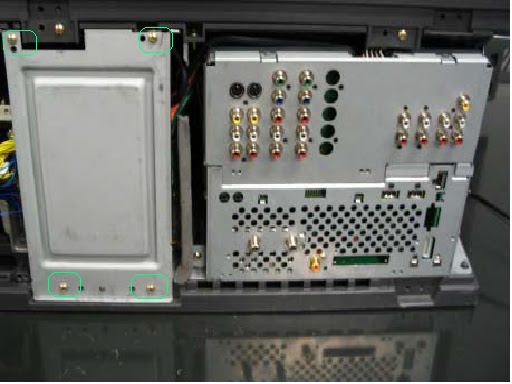
CHASSIS MOUNTING SCREWS REMOVAL
Remove 2 chassis mounting screws.
 Release Cable clamps and disconnect CE connector.

On the Right side of the chassis (From rear)

- Release AC cord mounting.
- Unplug 'ES1' connector to the speakers.

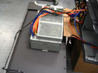
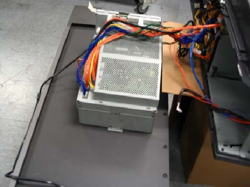
Chassis removal from the cabinet.
- Carefully rotate the chassis clockwise to slide it from the cabinet.
MODEL WD-52527WD-52528WD-62527WD-62528
Complete chassis removalTo completely remove the chassis from the cabinet, the following connectors must be unplugged.
- PL plug to the Ballast; on the left side of the chassis.
- KA plug from the PWB-RISER; right side of the chassis.
- FB, FC and J8F01 at the PWB-FORMAT; right side of the chassis.

