
- Check whether MAIN PCB is connected to SUB PCB(PA901to P901).
- Connect 9-PIN serial cable to the serial port of the computer.
- Connect the opposite end of the serial cable to RS-232C port of SUB PCB.
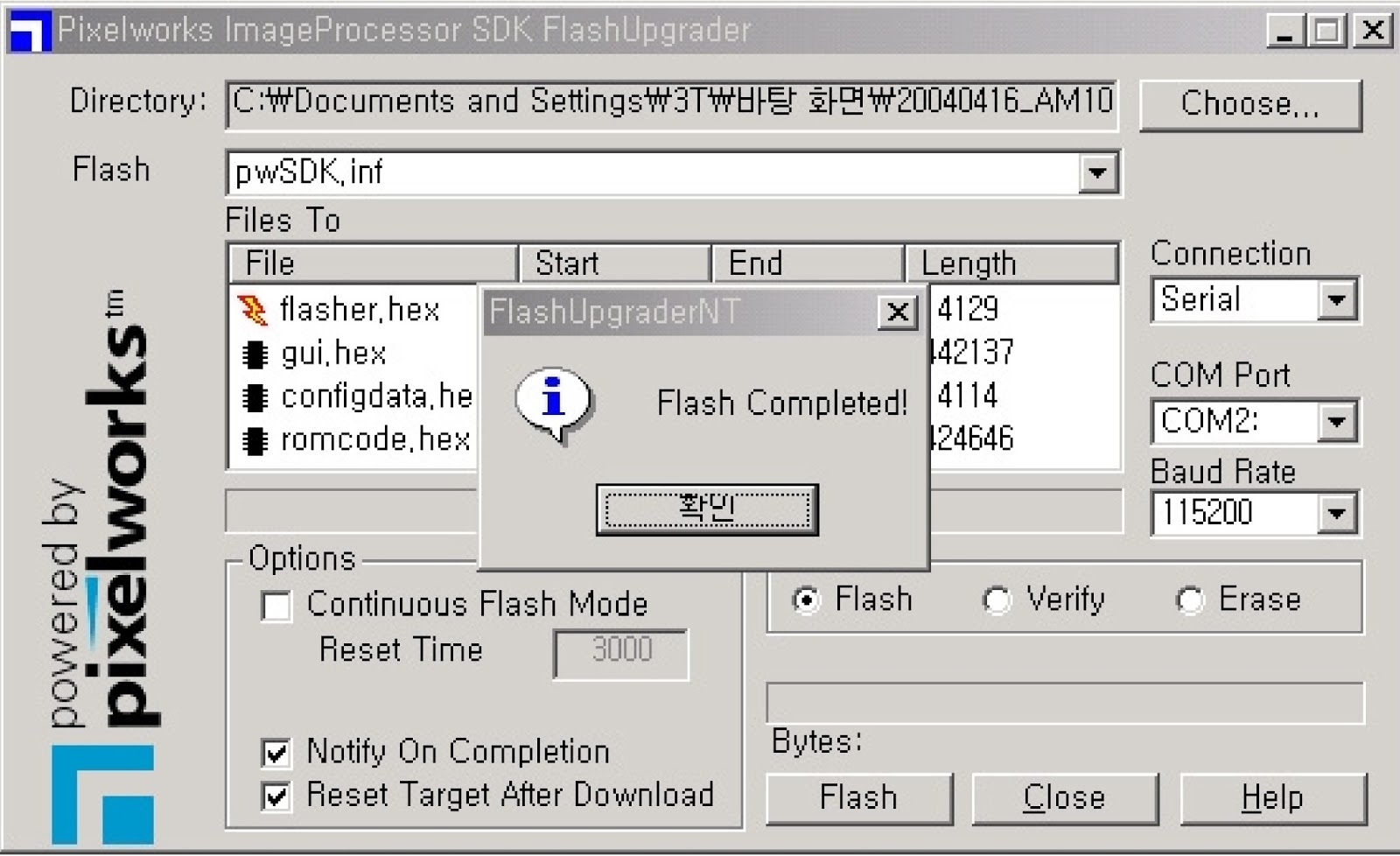
- Run Flashupgrader.exe in the PC to execute the program as shown below.

- Select current Upgrade file
- Click “Choose...” button to select the file you want to upgrade.
- Select the file (pwSDK.inf) that you want to upgrade.

- Select correct COM Port and Baud Rate(115200) as shown below. Then press Flash button to finish setup.

- Turn on the ac power and then upgrade program will start the download as shown below.

- When the upgrading is complete, a window (below) will be opened. Press “Finish” button to complete the process.
TO ENTER SERVICE MODE
- Press “ <VOL ” à “ MUTE ” à “ RECALL ” à “ MUTE ” button of remote controller (R-53J17) {OR} Press “S9 ”button of SERVICE REMOTE CONTROLLER.
- In the first line, there is the model name and the version of the upgraded program on the PDP set.
- The automatically set offset values may different from the default value depend on B/D. However, the main B/D should be replaced or contact Kunpo R&D center in Korea if the OFFSET values differ more than ±20 from default value.
RESET
- Level 1 –Resets all data in E2PROM other than HDCP key, EDID, RGB offset and YPbPr offset of Pw3300_1.
- Level 2 –Resets all data in E2PROM other than the exception of Level 1 and Pw318B_1.
- Factory – Resets the data of auto search, language setting, time setting, and the user menu values that could be reset by ‘Initialize’ function in Feature mode.
POWER ADJUSTMENT
- Power Adjustment – Adjusting to standard power voltages, which are written in the upper right side of PDP module. PDP module makers while producing already adjusted these values. Therefore, if there are some problems in picture after adjusting, you should classify that PDP module as a fault and contact to PDP module maker.
- Input Video Pattern – 100 IRE Full White Pattern.
Voltage Adjustment Label

Vs (Sustain Voltage) : Discharge Sustain Voltage
- Measurement Equipment : Digital Volt Meter (DC volt mode)
- Adjusting TP : TP204
- Adjusting Location : RV203
- Optimum Adjusting Voltage : The voltage which is written in the label located in upper right side of the PDP module. (Typical Voltage: 187V)

Click on image to Enlarge
High voltage S/W
- Do not touch while operating
- When replacing a power board make sure to check these switches. High voltage S/W à “HIGH”