
DVD PLAYER TROUBLESHOOTING and REMOVAL PROCEDURE
The DVD player is located on the front right hand side, just below the screen. If the Open/ Close button is pressed with the set turned off, the set will turn on and enter the DVD player screen. If the set is on and the Open/Close button is pressed, the set will enter the DVD player screen.
- The picture below shows the 46W500 with the front speaker grill removed. The Speaker grill simply pulls off in the forward direction.

- The picture below shows a close up view of the DVD player and the escushions surrounding the player that must be removed to gain access to the DVD player.

- The picture below shows the DVD player Front Controls dropped down. This allows access to to the top Left hand screw to remove the DVD player.

- The picture below shows a close up view of the DVD player and the escushions surrounding the player that must be removed to gain access to the DVD player.

- The picture below shows the screws to remove after the front escushion has been removed to remove the DVD player.

- The picture below shows the DVD player dropped down with it's connectors identified. Use the Flow Charts to identify locations for testing.

- The picture below shows the DVD player removed and separated from the PTV.

- The picture below shows the DVD player removed and viewed from the top. Note the Screws to remove the Top cover and to separated the DVD player from the Power Supply PWB below.

- The picture below shows the DVD player removed and viewed from the top. Note the Screws to remove the Top cover and to separated the DVD player from the Power Supply PWB below.

- The picture below shows the top cover removed. It reveals the DVD player ribbon cables. These cables must be removed to separated the DVD player from the Power supply PWB. Note the Black Arrow. This Ribbon cable does not need to be removed. It is from the Optic assembly.

- The picture below shows the screws to remove to separated the DVD Player from the Power Supply PWB below. NOTE: The three screws holding the DVD Player to the metal frame have nuts on the bottom. Do not remove these screws.

- The picture below shows the screws to remove to separated the DVD Player from the Power Supply PWB below. NOTE: This picture is showing the screws on the bottom side of the DVD Player

- The picture below shows the DVD Player separated from the Power Supply PWB.

- The picture below shows the DVD Player Power Supply PWB. This also identifies key components on the Power Supply PWB.
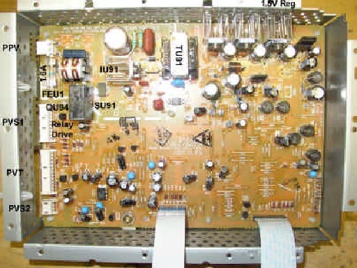
- The picture below shows the DVD Player Power Supply PWB separated from the DVD Player. This allows access to the connectors and for Troubleshooting the Power Supply. Return to the DVD player Troubleshooting Index to see Flow Charts. This picture shows how to check for AC applied to the Power Supply PWB. Other checks can be made this way and access to the check points are made much easier with the Power Supply separated from the DVD player.

By
plugging in the PPV connector AC is applied and the on board power supply can
operate. The PVS1 must also be
connected so that STBY +5V (from the PTV) can be applied to pin 2. Or an external +5V can be used. Note: Pins 5
and 8 of PVS1 is used as ground. To
turn on the Power Supply, apply a 2.2 K ohm resistor between pin 2 (+5V) and
pin 3 (Power On 3). This simulates a Power On command from the PTV
microprocessor. This will activate the relay driver (QU94) to turn on the DVD
power supply. At this point, check the following voltages.
DVD +9V: PAA1 connector pin 14 and 15. This checks
IU96.
DVD +5V: PAA1 connector pin 13. This checks IU95.
DVD +1.5V: PAA1 connector pin 1, 2 and 3. This checks
IU94.
DVD +3.3V: PAA1 connector pin 4 and 5. This checks EU91
protector.
No comments:
Post a Comment