
DISSASSEMBLY
- Turn off the power to the system and all peripheral.
- Unplug the AC adapter and all power and signal cables from the system.
Click on the images to Enlarge.
Removing the TV Stand
- Release the four screws fastening the TV stand.
- Then pull out the TV stand.


Removing the I/O Cover
- Release those screws marked in yellow for removing the I/O cover.
- Slide the I/O cover shown as arrows then detach it.


Removing the Rear Cover
- Release those screws as shown for removing the rear cover.
- Then lift the rear cover.


Removing the ESD Shield Top
- Release the nine screws securing the ESD shield top.
- Then lift the ESD shield top as shown.


Removing the Main Board and I/O Board
- This is the upper view of the main board and the location of those connectors.
- Disconnect the keypad to main board cable.
- Disconnect the speakers to main board cable.
- Disconnect the LVDS to main board cable.


- Disconnect the inverter board to main board cable.
- Disconnect the power board to main board cable.
- Disconnect the other power board to main board cable.
- Disconnect the power switch to main board cable.
- Release the ten screws fastening the main board and the I/O board.
- Remove them together then separate them.


Removing the Power Supply Board
- Release the seven screws fastening the power supply board and the cable then detach the power supply board.

Removing the PCD Holder
- Release those screws marked in yellow.
- Then lift the PCD holder as shown.


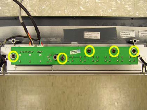
Removing the Keypad Board and the Power Button Board
- Release the five screws fastening the keypad board then detach it.
- Release the four screws fastening the power button board then detach it.
- They are the keypad board and the power button board with their corresponding cables.


Removing the LCD
- Release the four screws on the LCD brackets.
- Then lift the LCD.


Removing the Speakers
- Release the four screws securing the speaker.
- Repeat the anterior two steps to remove the other speaker.

