
The screws for the different components vary in size. During the disassembly process, group the screws with the corresponding components to avoid mismatch when putting back the components. When you remove the stripe cover, please be careful not to scrape the cover.
REMOVING STAND MODULE
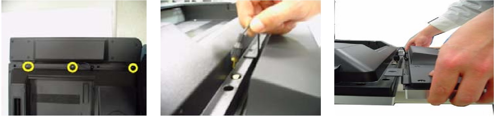
- Remove the four screws securing the TV stand cover.
- Remove the TV stand cover.
- Remove the six screws securing the TV stand module.
- Remove the TV stand module.

- Remove the four screws securing the base.
- Separate the base and the swivel assembly.

REMOVING THE I/O & MEDIA BOX
- Remove the two screws securing the I/O box.
- Remove the I/O box.
- Remove the two screws securing the media box.
- Remove the media box.

REMOVING SPEAKERS
- Remove the three screws securing left speaker.
- Disconnect the left speaker cable.
- Remove the left speaker.
- Remove the three screws securing right speaker.
- Disconnect the right speaker cable.
- Remove the right speaker.

- Remove the eight screws securing the speaker rear cover.
- Remove the speaker rear cover.
- Remove the four screws securing the speaker front cover.
- Remove the speaker front cover.

REMOVING SYSTEM FAN
- Remove the four screws securing the fan cover.
- Remove the fan cover.
- Remove the system fan.

NOTE: For new model, which doesn’t have the system fan,
please refer to following changes.
A thermal pad will be attached on the top shield.

- There will be vent and mylar decoration on the new wall mount.
- The screws for securing the fan cover will be shorter.


REMOVING WALL MOUNT ASS'Y
- Remove the sixteen screws securing the back cover.
- Remove the back cover.
- Remove the eight screws securing the wall mount assembly.
- Remove another eight screws securing the wall mount assembly.

- Remove the four screw nuts securing the wall mount as shown.
- Lift the wall mount up and slide it out.

REMOVING POWER BOARD
- Disconnect the cables from power board.
- Remove the three screws securing the power board.
- Remove the other three screws securing the power board.
- Remove power board.

REMOVING AUDIO BOARD & MAIN BOARD
- Disconnect all cables connected to the audio board.
- Remove the four screws securing the audio board.
- Remove the audio board.

- Remove the two screws securing the main board.
- Remove the other four screws securing the main board.
- Detach the main board from the unit.

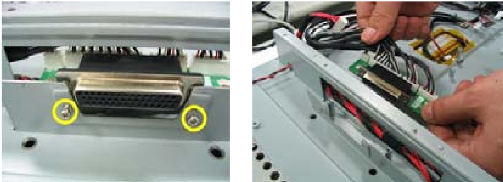
REMOVING THE INTERFACE BOARD
- Remove the two screws securing the interface board.
- Remove the interface board from the unit.
REMOVING BUTTON BOARD, EAR PHONE BOARD, SPEAKER BOARD
- Remove the three screws securing the button board wire clip.
- Remove the three screws securing the button board.
- Turn over the button and disconnect the cables connected to the button board and remove the button board.

- Remove the two screws securing the earphone board.
- Remove the earphone board.

- Remove the two screws securing the left speaker board.
- Remove the left speaker board cover.
- Remove the speaker board.
- Repeat the procedure for right speaker board.

REMOVING LCD MODULE
- Remove the button key.
- Remove the power lens.
- Remove the IR lens.
- Remove the two screws securing the left LCD bracket.
- Remove the two screws securing the right LCD bracket.


- Remove the sixteen screws securing the LCD module.
- Remove the LCD module from the unit.

- Remove the two screws securing the chassis middle.
- Remove the other screw securing the chassis middle.
- Disconnect the cable.
- Remove the chassis middle.

- Remove the three screws securing the left and right LCD bracket.
