SOFTWARE UPGRADE
Software writing and upgrade method
with ISP writing-device.
- Main board upgrade: connect a
four-pin wire of the ISP writing-device to Debug port(X806) on the main board;
Unit upgrade: connect VGA ports of the ISP writing-device and the main board,
enter factory menu and set “ISP Mode” to “ON”.
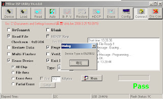
- Using Mstar writing-tool on line,
click “Connect” menu, if it displays “Device EN25B32“ as shown in fig, the
connection is success, if it fails, select “EN25B52” of “Device” manually and
press “Connect” again.
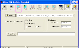
- Click “Read” and select the file written
(MERGE.bin for example) as shown in fig.
- Click “Auto”, select “All chip”,
“program” and other items as shown if fig.
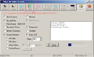
- Press “Run” to begin writing and
there are two steps: Erase and Program.
- If the process of writing succeeds,
it will display “Pass” near “Run” as shown in fig.
Repeat step 2) and 5) to write the program to
the other units without exit the ISP interface
UPGRADE BY USB PORT
- Make sure the USB device is
formatted as FAT32.
- Copy the program named Merge.bin to
USB device.
- Insert the USB device to USB port of
the unit, power on and select RF-ATV channel, begin USB upgrade after OSD
disappear. It will display blue when read the data from USB device, while
display red when write Flash. The flash must be pull out when display red. It
will flicker in red and blue if the process of writing is abnormal.
- The method are not applicable to all
the USB devices, try another one if a certain USB device is
inapplicable.
WORKING PRINCIPLE OF THE UNIT
Antenna reception PAL/SECAM signal
will be send to tuner TDA1616, which contains frequency turning, HF and IF
amplifier circuit and is controlled by master control IC MSD109 (comprises CPU)
through I2C bus. The analog IF signal via intermediate frequency amplifying,
video SAW filter K3953 and audio SAW filter K9656 to input to analog demodulate
IC (IF) R2A10406NP, after demodulating and output standard video signal TV-CVBS
and sound IF signal (SIF). TV-CVBS will
send to the master control IC MSD109 to video decode, deinterlace and scale,
then output LVDS level drive for panel display. The sound IF (SIF) will be fed
into MSD109, after demodulating, pre-amplifying, bass adjusting and volume
control, the sound signal will separate into L/R channels and input to earphone
amplifier BH3547F amplifying, then output two ways. One way will be sent to
earphone, another will be sent to digital sound amplifier R2A15112FP amplifying
then sent to speaker.
Antenna reception DVB-T signal will
be sent to tuner TDA1616, after frequency tuning, HF amplification, IF
amplification and SAW FILTER, output IF signal to demodulation chip CE6353, via
QAM demodulation, fed to MSD109 for information source decoding in the format
of standard serial TS stream.
HD video signal via decoding to A/D
conversion and OSD superposition, at last output LVDS drive level for panel
display. HD audio signal via decoder
built-in MSD109, resumed to multi- channel sound of Dolby AC-3. The audio
signal will be sent to back end to perform bass adjustment and volume control,
then it will separate into L/R channels and input to earphone amplifier BH3547F
amplifying, then output two ways. One way will be sent to earphone, another way
will be sent to digital sound amplifier R2A15112FP amplifying then sent to
speaker.
SV signal and the first path AV
signal switch automatically via S-terminal socket, the signal and the second
path AV signal will be fed to MSD109 to perform video decode, deinterlace and
scale, then output LVDS drive level for panel display. Audio signal from AV/SV via matched
resistance is fed to external audio switch HEF4052 to switch, then it is
directly sent to MSD109 to bass adjust and volume control, the sound will
separate into L/R
channels and input to earphone
amplifier BH3547F amplifying, then output two ways. One way will be sent to
earphone, another way will be sent to digital sound amplifier R2A15112FP
amplifying then sent to speaker.
PC and the second path YPbPr signal
are switched via external switcher PI5V330, then the signal and the first path
YPbPr signal will be sent to MSD109 A/D conversion, output R/G/B of 24 bit to back
end module to digital decode, image scale and OSD superposition, then send to
LVDS level drive for panel display. Sound
signal of PC/YPrPb via matched resistance and a-c couple are sent to MSD109 to
bass adjust and volume control, the sound will separate into L/R channels and
input to earphone amplifier BH3547F amplifying, then output two ways. One way
will be sent to earphone, another way will be sent to digital sound
amplifier R2A15112FP amplifying then sent to speaker.
Three HDMI video signals via
switcher PS321 are directly fed to the master control IC MSD109 to digital
decode, image scale and OSD superposition, then output LVDS drive level for
panel display. HDMI audio signal via
decoder built-in MSD109 is fed to back end to bass adjust and volume control,
the sound will separate into L/R channels and input to earphone amplifier
BH3547F amplifying, then output two ways. One way will be sent to earphone,
another way will be sent to digital sound amplifier R2A15112FP amplifying then
sent to speaker.


